)
UNAVCO Topcon GB-1000 Campaign Kit
UNAVCO Topcon GB-1000 Campaign Kit
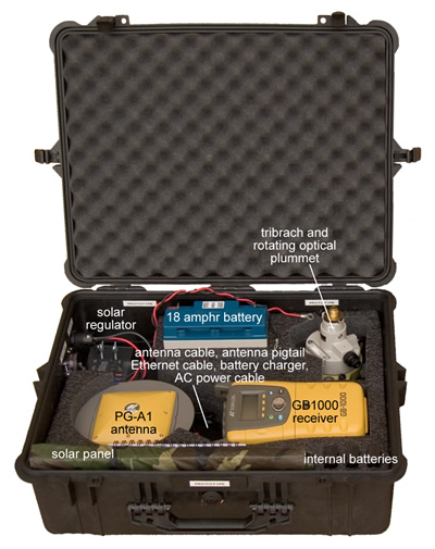
UNAVCO maintains 100 campaign GPS systems in order to support portable GPS deployments funded by the NSF’s EarthScope Science panel. Based on Topcon GB-1000 equipment, the systems have been designed for stand-alone temporary or semi-permanent deployment that will be used for densifying areas not sufficiently covered by continuous GPS and for responding to volcanic and tectonic crises. Six of the 100 systems are equipped with real-time kinematic (RTK) capability for such uses as rapid fault mapping and GIS-based geologic mapping. ANTENNA MONUMENTATION AND MOUNTS MUST BE REQUESTED SEPARATELY. See "Additional Resources" at the bottom of the page.
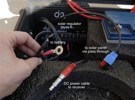
View of solar regulator and power cables, back left corner of the box.
Components
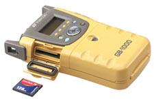
GB-1000 receiver, Topcon - Records GPS data received via the antenna.
Topcon GB-1000 Resource Page (includes e.g. software, firmware, and how-tos)
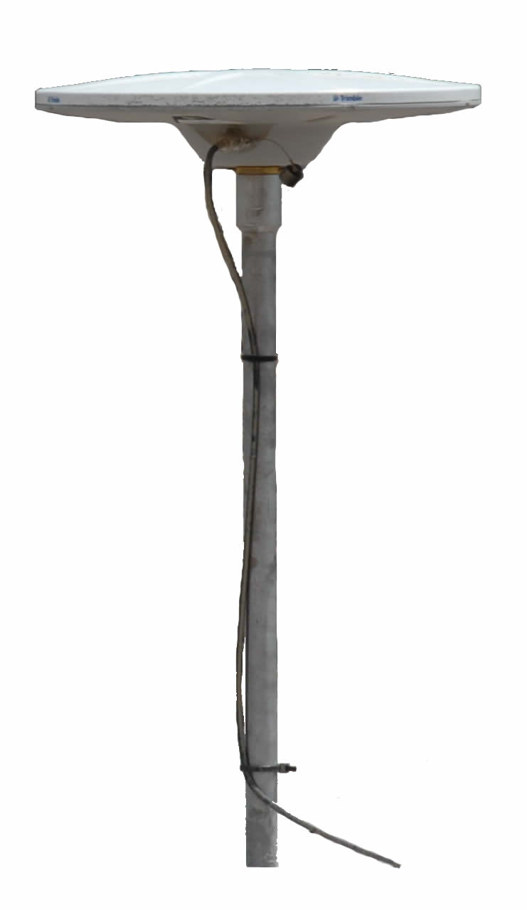
PG-A1 antenna, Topcon - Receives GPS data and transmits data to the receiver.
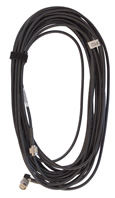
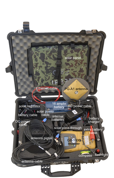
antenna cable (10 m TNC-TNC) - Transmits the data from the antenna to the receiver. Connect the 90-degree connector (if there is one) to the antenna and the straight connector to the antenna port (see below). Do not kink the cable; when coiling the cable, do not coil it around your hand and elbow.
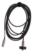
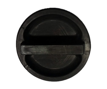
antenna pigtail (TNC-lemo) and port - Used to connect the antenna cable to the receiver via a weatherproof connection. Screw the port into the case. Connect the 1-pin lemo connector to the antenna port on the receiver by pushing it straight in. Any orientation will work. Remove the connector from the receiver by pulling straight out from the connector (not from the cable).
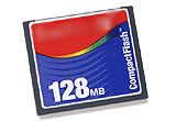
compact flash card - 1 GB, supplementing internal memory of 1 GB. At a rate of 15 s data collection, approximately 1.2 years of data can be stored between both memory options.
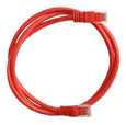
Ethernet cable - Used to communicate with the GB-1000 via a computer. Connect either end to the receiver and the other end to your computer. Note that both cross-over and straight Ethernet cables will work with the GB-1000, but not necessarily with your computer.
AC power adapter - Used to connect the receiver to AC (outlet) power.
DC power cable - Used to connect the receiver to DC (battery) power. This cable is already connected to the solar regulator; connect the free end to the receiver’s power port after the battery has been attached to the solar regulator by aligning the red dot on the connector to the red dot on the port; push straight in. To disconnect, pull straight out while holding the part of the connector closest to the receiver. Never pull from the cable; the connector with not come out.
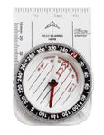
compass - Used to align the GPS antenna to true north.
How to use declination to align the GNSS antenna to true north
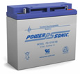
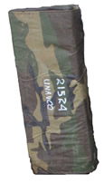
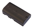
18 amp hr battery (12 volts) - Will power the receiver and GPS antenna for approximately 1.9 days in optimal conditions. Battery life decreases significantly in cold weather. Do not allow conductive material (e.g. a piece of metal) to contact both terminals at the same time as this will short the battery.
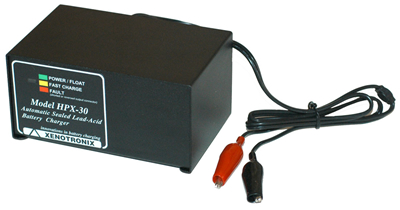
battery charger - Will completely recharge a battery at 11 volts (the shut-off voltage for the receiver) in several hours. Make sure the switch on the back is showing the appropriate voltage for your region (e.g. 120 volts in US, 240 in most of Europe). If the battery charger fails, check this switch and change the fuse as needed. Connect the cable to the battery terminals (red alligator clip (connector) to the red/positive terminal and black clip to the black/negative terminal). Do not allow the connectors to touch each other when the charger is plugged in.
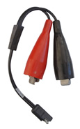
extra battery cable - Used to connect an extra battery to the solar regulator. Connect the alligator clips to the battery terminals (red to the red/positive terminal and black to the black/negative terminal); connect the other end to a lead coming from the solar regulator.
solar panel - Charges the battery when there is sufficient sunlight. Will maintain a 12+ volt charge on the battery. With 12 hours of daylight, the 18 amp hr battery and the solar panel should provide a sustainable power source for an extended period of time (weeks to years).
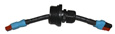
solar pass-through - Used to connect the solar panel to the solar regulator via a weatherproof connection. Screw the middle connector into a port on the box; connect the solar panel to one end and the leads to the solar regulator to the other.
Vendor info:
 Feed through Assbly
Part# 41215-00 Rev , Cases Plus, Inc., Phone # 800-982-1880
Feed through Assbly
Part# 41215-00 Rev , Cases Plus, Inc., Phone # 800-982-1880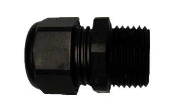 Half inch Cable gland
fitting Part #CD13NA-BK-N-O, Home Depot electric dept
Half inch Cable gland
fitting Part #CD13NA-BK-N-O, Home Depot electric dept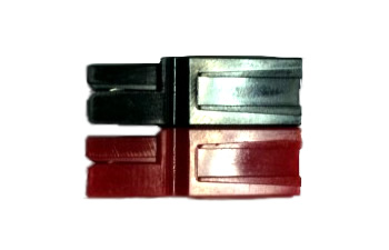 Red and black power
connector Part # 1330, C W Distribution Inc., Phone #
218-525-2205
Red and black power
connector Part # 1330, C W Distribution Inc., Phone #
218-525-2205
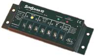
solar
regulator
- Regulates
the power from the solar panel to the battery and the battery to the
receiver. All power cables are already connected to the solar regulator
(see photo, above). Connect the lead from the solar pass-through (above)
to the lead on the regulator. Connect the battery leads to the battery
terminals
(red ring terminal to red/positive terminal, black ring terminal to
black/negative
terminal). After the power sources are connected, connect the DC power
cable to the receiver as described above.
solar regulator
- Regulates the power from the solar panel to the battery and the battery to the receiver. All power cables are already connected to the solar regulator. Connect the lead from the ... Connect the battery leads to the battery
terminals (red ring terminal to red/positive terminal, black ring terminal to
black/negative terminal). After the power sources are connected, connect the DC power cable to the receiver as described above.
internal batteries
-
Regulates the power from the solar panel to the battery and the battery
to the receiver. All power cables are already connected to the solar
regulator (see photo, above). Connect the lead from the solar pass-through (above) to the lead on the regulator. Connect the battery leads to the battery terminals (red ring to red/positive terminal, black ring to
black/negative terminal). After the power sources are connected, connect the DC power cable to the receiver.
flashlight - Included in some kits.
Additional Resources
UNAVCO Resources: GNSS Station Monumentation
Geodetic monuments and markers; this is principally a resource for permanent station monumentation but includes campaign options as well.
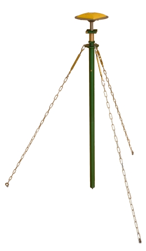
UNAVCO Resources: GNSS Antenna Mounts
An
antenna mount is used to couple the GPS/GNSS antenna to the survey
point. Different mounts are appropriate for different survey types.
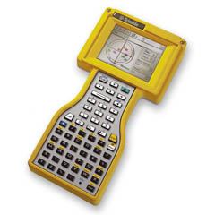
UNAVCO Resources: GPS Survey Controllers
Survey controllers can be used to incorporate metadata into a GPS survey and are commonly used for real-time kinematic, post-processing kinematic, and fast/rapid-static surveys.