
Vaisala - How to integrate the Vaisala WXT520 with the Topcon NET-G3
Integrating the Vaisala WXT520 with the Topcon NET-G3
Equipment needed
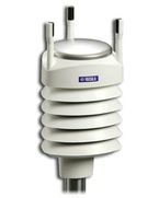
Vaisala WXT520 Met-Pack
WXT520 serial cable
9V battery
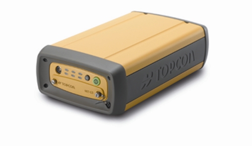
NET-G3 receiver
Software Needed
PC-CDU Version 7.12 (Build: Dec. 21, 2007) (.zip)
Vaisala Configuration Tool Version 2.01 r. 9 (see link below)
Configuring the Vaisala WXT520
We first describe how to configure the WXT520 to output a single XDR NMEA v3.0 0183 message containing the following values: Pressure, Temperature, Humidity, Wind Speed, Wind Direction, Rain Accumulation & Hail Accumulation. The reason we choose an XDR NMEA v3.0 0183 message is because this is the only type of met message the Topcon NET-G3 can receive.
One way to configure the WXT520 is using the Vaisala Configuration Tool. The latest version at the time of writing this is Ver. 2.01 r.9; it can be downloaded at http://www.vaisala.com/services/software.html.
Connect the WXT520 to a Windows computer and start up the Configuration Tool. If you don’t see any readings coming then you will have to go into Configuration Setup via File → Configuration Setup. The following window will appear:
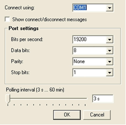
Figure 1: COM port settings for communicating with a WXT520 using the Vaisala Configuration Tool.
Confirm the settings above and click OK. In the main window you should now see some values being read by the Configuration Tool from WXT520.
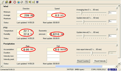
Figure 2: Main window of the Vaisala Configuration Tool. The circled values are read automatically from the WXT520 if it is set up to output Wind, PTU and Precipitation.
Now that the Vaisala Configuration Tool is communicating with the WXT520 we can start setting it up to output the XDR NMEA v3.0 0189 message.
From the Settings drop-down menu select “Device…” The following window will appear; check that the settings are as they are shown here:
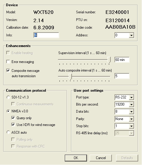
Figure 3: The Device Configuration window for the WXT520. The key settings in this window are the “Composite Message auto transmission” checkbox and the “Auto Composite interval”. Set the interval to what you need it to be. The next key setting in this window is the “Communication protocol”. Be sure to select “NMEA v3.0” and check the “Query Only” and the “Use XDR for wind message”.
Note that we have checked the “Query Only” box in the Communication Protocol section. This is so that Wind, PTU and Precipitation data don’t come through unless the WXT520 is queried for them. Also note that we check “Composite message auto transmission” so the composite message will automatically be output but the individual Wind, PTU and Precipitation will not. This is crucial. After you are done click OK.
We now configure the Wind, PTU and Precipitation sensors within the WXT520. From the Settings drop-down menu select “Sensors…” You will get the following window. Check that the settings are as they are shown here:
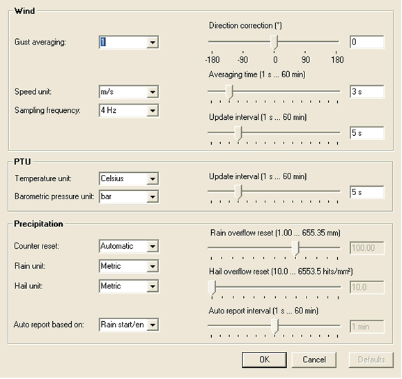
Figure 4: WXT520 sensor settings. The main things to change here are the PTU “Temperature Unit” and the “Barometric pressure unit”.
Now we move on to the final step in configuring this WXT520, the Message Settings. From the Settings drop-down menu select “Messages…” The following window will appear. Check that the settings are as they are shown here:
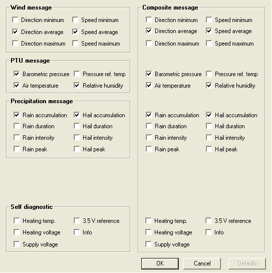
Figure 5: The Wind, PTU and Precipitation message boxes are the values that are queried by the Vaisala Configuration Tool as in Figure 2. The values under the Composite Message Section are the values that will be output to and combined with the GPS .tps files being recorded on the Topcon NET-G3.
The WXT520 met-pack is now configured to output messages that look like:
$WIXDR,A,282,D,1,S,0.1,M,1,C,22.0,C,0,H,23.0,P,0,P,0.8211,B,0,V,0.00,M,0,V,0.0,M,1*42
This message will be read by the Topcon NET-G3 and injected into .tps files being recorded on the GPS receiver.
In order to check that these messages are being output at the specified rate, connect to the WXT520 via hyperterminal. Below are the settings you need to set in the hyperterminal. From within hyperterminal, click the drop-down menu File and select “Properties”.
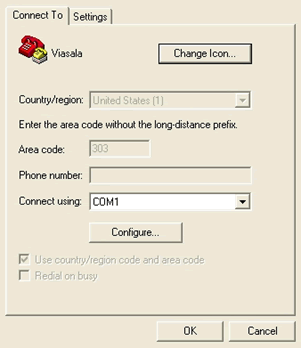
Figure 6: Beginning menu to configure a hyperterminal to communicate with the WXT520.
From here click on the “Settings” tab at the top. The following window will apper. Check that the settings are as they are shown here:
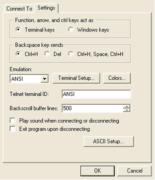
Figure 7: Set these values on your hyperterminal.
From this window click on “ASCII Setup…” to get the following menu. Check that the settings are as they are shown here:
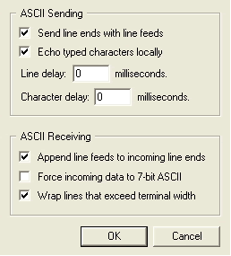
Figure 8: These settings will allow you to send commands to the WXT520 via hyperterminal.
Now that all of this is set, click OK until you get back to the main hyperterminal menu. You are now ready to connect to the WXT520. Once you connect you will start seeing the Composite Message come through to the terminal.
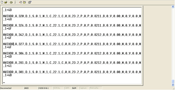
Figure 9: Composite message coming through hyperterminal.
Configuring the NET-G3
Connect the DB9-Fisher RS232 cable that comes with the Topcon receiver to a serial port on your computer and to the front of the NET-G3. Start PC-CDU and connect to the receiver. From the Configuration drop-down menu, select Receiver. The configuration window will appear; select the Ports tab at the top and set the serial port as shown here:
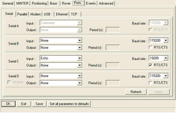
Figure 10: Since we connected the WXT520 to serial port C on the back of the receiver we have set that serial port to communicate with the WXT520 at the same baud rate we set the WXT520 to be. We have also selected the Input to be Echo and the output to be None. Make sure you DO select RTS/CTS.
After you have configured the serial port on the NET-G3 click OK and this will take you back to the original window you started at.
We now need to send some GRIL commands to the NET-G3 to set a few more things on the serial port. From the File dropdown menu select Manual Mode; this will open up a terminal where you can issue GRIL commands to the receiver. We need to enable the wrapped echo mode, using the following command:
set, dev/ser/c/ewrap, on
Now we set the NET-G3 to listen for the NMEA XDR messages that the WXT520 is sending out every 5 seconds. To do this we send the following command:
dm, dev/ser/c, misc/MET3
The command above will query the listen for incoming NMEA XDR message. NOTE: We use misc/MET3 because we are disabling the NET-G3 from querying the MET3 and instead setting it to listen to anything that comes in through the serial port.
Now we can test whether or not the WXT520 and the NET-G3 are communicating. To do this send the following command:
set, dev/ser/c/echo, /cur/term
The command above will start outputting messages every 5 seconds to the terminal in the following form:
05Ac$WIXDR,A,252,D,1,S,0.2,M,1,C,23.8,C,0,H,18.8,P,0,P,0.8424,B,0,V,0.00,M,0,V,0.0,M,1*45
C0
05Ac$WIXDR,A,250,D,1,S,0.3,M,1,C,23.8,C,0,H,18.8,P,0,P,0.8424,B,0,V,0.00,M,0,V,0.0,M,1*46
12
05Ac$WIXDR,A,249,D,1,S,0.2,M,1,C,23.8,C,0,H,18.9,P,0,P,0.8424,B,0,V,0.00,M,0,V,0.0,M,1*4E
D2
05Ac$WIXDR,A,236,D,1,S,0.3,M,1,C,23.8,C,0,H,18.9,P,0,P,0.8424,B,0,V,0.00,M,0,V,0.0,M,1*47
4D
Now you know that the two devices are communicating. At this point you are ready to redirect these messages to the GPS file currently being logged. To do this issue the following command:
set, dev/ser/c/echo, /cur/file/a
At this point the WXT520 data is being injected into the currently logged GPS file every 5 seconds. You can download the file currently being logged and run the following command to extract the met data:
teqc -top tps +met $filename.met $filename > $filename.09o
You should see something like the following in the $filename.met file:
     2.11           METEOROLOGICAL DATA                     RINEX VERSION / TYPE
teqc  2008Oct2      nic                 20091103 21:55:02UTCPGM / RUN BY / DATE
Linux 2.4.20-8|Pentium IV|gcc|Linux|486/DX+                 COMMENT
                                                            MARKER NAME
     7    PR    TD    HR    WS    WD    RI    HI            # / TYPES OF OBSERV
                                                  0.0    PR SENSOR MOD/TYPE/ACC
                                                  0.0    TD SENSOR MOD/TYPE/ACC
                                                  0.0    HR SENSOR MOD/TYPE/ACC
                                                  0.0    WS SENSOR MOD/TYPE/ACC
                                                  0.0    WD SENSOR MOD/TYPE/ACC
                                                  0.0    RI SENSOR MOD/TYPE/ACC
                                                  0.0    HI SENSOR MOD/TYPE/ACC
        0.0000        0.0000        0.0000        0.0000 PR SENSOR POS XYZ/H
                                                            END OF HEADER
 09 11  3 21 54 24  842.4   23.6   21.5    0.1  334.0    0.0    0.0
 09 11  3 21 54 29  842.4   23.6   21.5    0.1  337.0    0.0    0.0
 09 11  3 21 54 34  842.4   23.6   21.5    0.1  325.0    0.0    0.0
 09 11  3 21 54 39  842.4   23.6   21.5    0.1  337.0    0.0    0.0
 09 11  3 21 54 44  842.4   23.6   21.5    0.1   36.0    0.0    0.0
 09 11  3 21 54 49  842.4   23.6   21.6    0.1    1.0    0.0    0.0
 09 11  3 21 54 54  842.4   23.6   21.6    0.0   88.0    0.0    0.0
 09 11  3 21 54 59  842.4   23.6   21.6    0.1  355.0    0.0    0.0
nf2009