
Power - Wind Power Testing at UNAVCO through 2005, Phase 1
Wind Power Testing at UNAVCO through 2005, Phase 1
The purpose of phase one of the wind generator testing is to become familiar with the general setup and power characteristics of the system. This includes tower construction, cabling, regulation and integration with a solar system. Though not a likely field system, this setup, located in a generally windy location south of Boulder, demonstrates constant and gusty wind conditions as well as stale weather conditions.
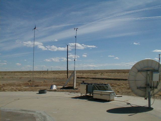
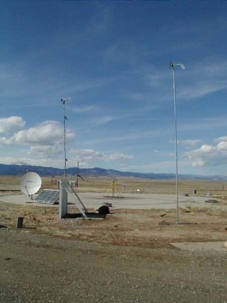 System: The Marshall Test site contains a power system which includes a battery bank, solar and wind charging systems. A permanant VSAT dish is located to test VSAT control boxes before they are sent out. Various receivers and radio modem systems are also tested at this location. |
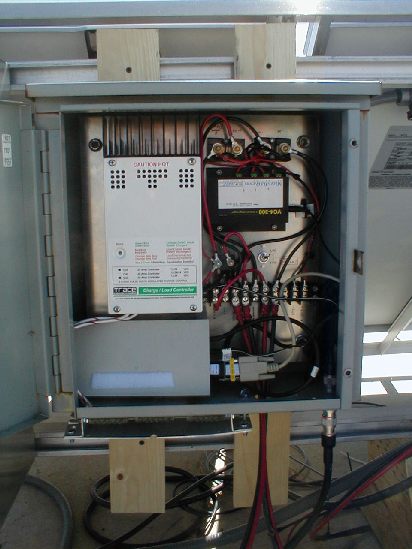 Panel:This is the power panel for the wind system. It contains a C40 Diversion Charge Controller (white w/ fins), 2 shunts (black, top) to measure current from generator and solar regulator), data logger (black box, middle), 50A breaker (grey, next to C40), stop switch, Freewave radio modem (grey, bottom) and diversion load (silver, attached to bottom of box). |
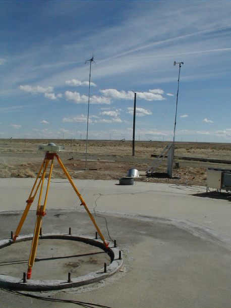
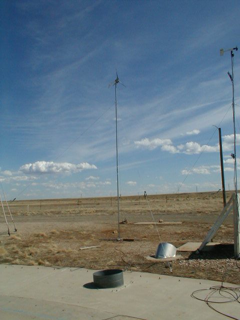 Tower: The tower is 24 feet tall, guyed with 4 5/32 braided stainless cable. For this setup, the anchor points are 4 30" steel auger style ground anchors. Each guy wire is approximately 21’ in length. The pole is constructed of two 10’ sections coupled together and one 4’ section clamped to the top, attached to the generator. Three 8 guage wires run inside the tower to a junction box at the botom, where there is a lightning arrestor. |
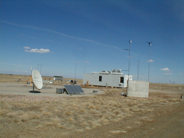
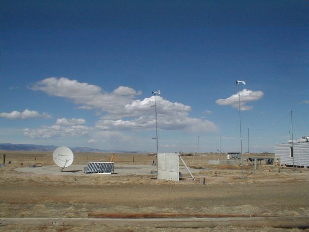
Other site photos:
Configuration:
This site serves as a test site for our power, GPS and communications equipment. The configuration during the test includes:
Load
2 GPS receivers: 1 Ashtech Micro-Z, 1 Ashtech Z12. Both shared 1 Ashtech choke ring antenna
2 Freewave radio modems transmitting at full power
1 Nanometrics VSAT system
Power Source:
4 55W solar panels
1 Southwest Wind Power Air Industrial Generator on 24’ tower; 30" auger style ground anchors
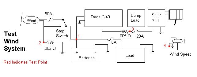
Power Regulation:
1 Trace C-40 diversion controller - hooked directly to battery bank
1 Flexcharge 30A Solar Regulator - hooked between solar panels and battery
Batteries:
8 Deep Cycle 90 amp hour batteries
Data Logging:
1 MicroDaq 4-channel data logger - self powered, monitored battery voltage, wind speed and shunt voltages on the generator and the solar system (to measure current from those sources). Output is RS-232 via one of the freewave radios to UNAVCO facility.
Data and Graphs
Graph Key
April 14, 2002 - Duration: 1 day, 5 second intervals
May 6, 2002 - Duration: 14 days, 1 minute intervals
May 28, 2002 - Duration: 8 days, 30 second intervals
Results
Going into the test, it was known that the system load would not be enough to need the full capacity of the generator and solar panels combined. Because the site experiences non-windy periods, unhooking the solar system was not an option.
Throughout the test, the system appeared to perform reliably and consistently. The only problem we had appears to have been a defective circuit breaker. It was replaced with a higher rated, self resetting unit. Ice, extreme gusts and other weather appears to have not affected the unit. During this test, no lighting storms had occurred.
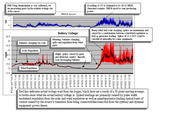
From the data obtained and seen in the graphs linked to above, it is seen that the system displayed two unwanted characteristics:
unwanted voltage spikes during high-wind/gusty periods
competition between the two regulators
A power filter can easily solve the first issue without changes to the system setup, however, the second issue is a little more complicated. Because both controllers are attempting to regulate the batteries using phased and pulse width modulated techniques, the current draws from the regulators are constantly changing. Since the regulators are not clocked together, their readings are taken at different points in each cycle. This appears to be causing interference in the charging cycles of each device.
Fortunately, phase two should prove to weed out the issues seen above as we will construct a likely field configuration and reduce the output of the generator to match the system power requirements. This will be done by disconnecting one or two of the three internal windings of the generator. If the overall power delivery of the solar and wind units are kept under 40 amps, then a single Trace C-40 will be able to regulate both power sources.
Send questions or comments about this page to Support (support![]() unavco.org).
unavco.org).