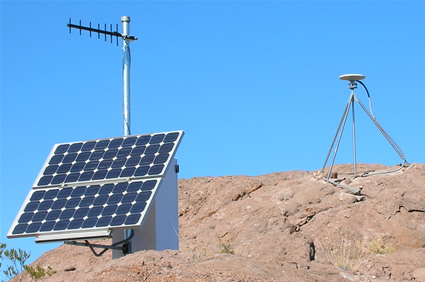
Directional (Yagi) Antenna Summary
Directional (Yagi) Antenna Summary
The directional antenna has a distinct gain pattern in the direction perpendicular to the elements, i.e. in the direction of the 7/8" diameter antenna boom. The radiation pattern for the directional Yagi antenna reveals a strong backlobe as well as frontlobe in both the horizontal and vertical polarization, as seen in the E-plane and H-plane respectively. Care should be taken to avoid placing the radio or cellular directional antenna so that these lobes will interfere with the reception of the GPS signals. The antenna bandpass filter for the L2 GPS frequency (1227.60MHz) will let some of the 800-900MHz radio or cellular frequency through and interfere with the reception of the GPS signals. The directional Yagi antenna has a gain of 12dB while the GPS signal only has a gain of -163dB when it reaches the antenna, thus a correct separation of the communication antenna and the GPS antenna are of vital importance for the quality of the GPS data. If the site configuration makes this separation difficult a corner reflector antenna can be used instead of the conventional directional Yagi antenna. The corner reflector antenna has a reduced backlobe because of its reflective shield and also a reduced forward gain compared to the directional Yagi antenna. The corner reflector antenna gain is 8.5dB compared to 12dB for the directional Yagi antenna.
Directional Yagi Antenna model for UNAVCO radio modem/transceiver sites:
6 element directional Yagi antenna, 896-960MHz, 12dB gain, Larsen part number YA5 900

A Yagi antenna is used to transfer data via CDMA modem from site CDVV near Socorro,
New Mexico to New Mexico Tech.
Directional Yagi Antennas for UNAVCO cellular phone modem sites:
6 element directional Yagi antenna, 824-896MHz, 10dB gain, Maxrad part number MYA-8256
Broadband Corner Reflector antenna, 806-896MHz, 8.5dB gain, Maxrad part number MCR-806
)