Custom Cavity-Type Notch Filter for Mitigating GPS/GNSS Interference from Iridium Data Transmitters
The Iridium satellite communication system uses the 1616-1626.5 MHz band to uplink with orbiting communication satellites. UNAVCO Inc. uses iridium communication links to download GPS data from remote GPS stations located at high latitudes. The L1 frequencies broadcast by GPS, Galileo and GLONASS satellites are 1575.42 MHz, 1575.42 MHz and 1602 MHz + n × 0.5625 MHz, respectively (each GLONASS satellite uses a unique frequency). The proximity of the Iridium frequency band with the L1 frequencies of the GPS, Galileo and GLONASS systems leaves GNSS receivers susceptible to interference from Iridium data transmissions. Interference from Iridium transmissions can cause cycle slips and loss of lock on the carrier and code phases, thereby degrading the quality of GNSS observations.
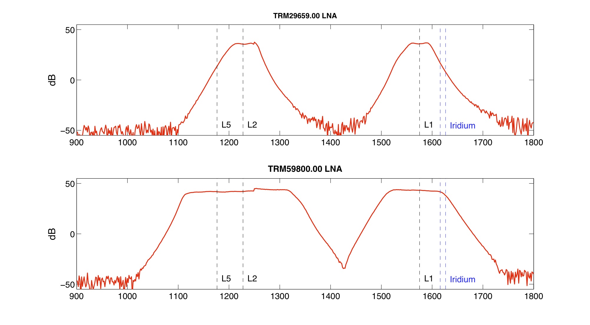
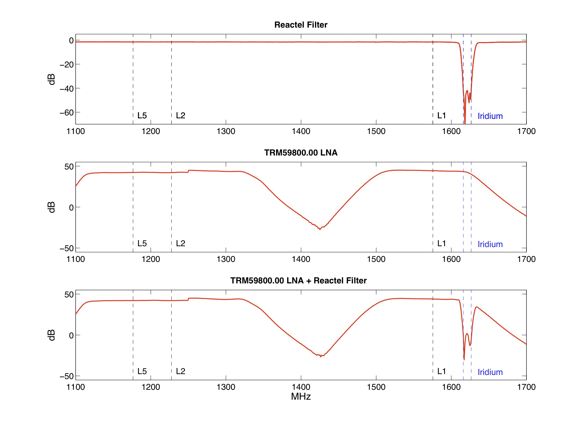
The broader gain pattern of the Low Noise Amplifiers (LNA) installed in many newer GNSS receivers/antennas (shown below) can increase the impact of near-band RF interference on tracking performance. Our testing has shown that the quality of data collected at sites collocated with iridium communications is highly degraded for antenna separations exceeding 100m. Using older GPS antenna models (e.g. TRM29659.00) with newer GNSS enabled receivers can reduce this effect. To mitigate the effects that iridium data transmissions have on receiver tracking performance, we tested a custom cavity-type notch filter designed to attenuate the Iridium RF band. The filter has a >20dB rejection at 1616-1626.5 MHz. Test results when using the filter have shown excellent GPS data quality at antenna separations of ~30 m. Determining what impact the filter has on GLONASS and Galileo observations will require further testing. Future investigations will also include alternative RF mitigation methods, including RF shielding.
Above: A custom cavity-type notch filter designed to mitigate the interference caused by Iridium communication transmissions.

Above: Gain vs. frequency for a Trimble GPS Choke Ring antenna LNA compared with a Trimble GNSS Choke Ring LNA. The gain pattern for the newer GNSS choke ring has been widened to improve the tracking of GNSS signals.

Above: Gain (dB) vs. frequency (MHz) measurements for three different Device Under Test (DUT) combinations. 1) Reactel custom cavity-type notch filter. 2) Low Noise Amplifier (LNA) from a Trimble GNSS Choke Ring antenna. 3) Trimble LNA + the Reactel notch filter. Dashed black lines indicate the L5, L2 and L1 GPS frequencies. The dashed blue lines show the frequency band used by Iridium communications for uplinking to a satellite. The notch filter has <0.5 dB insertion loss at the L1, L2 and L5 frequencies, and has a greater >20 dB rejection at 1616-1626.5 MHz.
)