Update: GPS/GNSS Interference From Iridium Data Transmissions
The Iridium satellite communication system broadcasts in the 1610 to 1626.5 MHz band. UNAVCO Inc. uses iridium communication links to download GPS data from remote GPS stations. The L1 frequencies broadcast by GPS, Galileo and GLONASS satellites are 1575.42 MHz, 1575.42 MHz and 1602 MHz + n × 0.5625 MHz, respectively (each GLONASS satellite uses a unique frequency). The proximity of the Iridium frequency band with the L1 frequencies of the GPS, Galileo and GLONASS systems leaves GNSS receivers susceptible to interference from Iridium data transmissions. Interference from Iridium transmissions can cause cycle slips and loss of lock on the carrier and code phases, thereby degrading the quality of GNSS observations. In 2008, UNAVCO staff members observed that the % of slips/# of observations increased as the distance between a Trimble GPS choke ring antenna (TRM29659.00) and an Iridium antenna decreased. From those observations they suggested that Iridium and GPS antennas should be separated by >30 m to minimize cycle slips caused by the interference from Iridium data transmissions.[1] A second test conducted in 2/09 using a newer Trimble GNSS choke ring antenna (TRM59800.00) and a Trimble NetRS receiver showed similar results to the previous test despite the wider frequency range of the newer antenna. Cycle slips were observed to be decreasing as the GPS antenna was placed further away from a bank of Iridium antennas. Cycle slips decreased to zero over an hour-long session when the GPS antenna position was a distance of 15 m from the bank of Iridium antennas.
The purpose of this update is to present new observations showing GNSS tracking interference from Iridium data transmissions. These results show that two Galileo enabled receiver models (Leica GR10 and Trimble NetR9), when connected to GNSS compatible antennas, have increased sensitivity to interference from Iridium transmissions compared to older receivers (NetRS, NetR5, NetR8, etc.). Frequent loss of lock indicators and ionospheric delay slips were detected by UNAVCO’s pre-processing software, TEQC, with both the GR10 and NetR9 receivers. The distance between the Iridium transmission source and the GNSS antenna was ~35 m for all of the observations. Our results indicate that the old recommendation of a >30m antenna separation will not prevent interference from occurring with newer Galileo enabled receiver designs. Future testing will be necessary to determine the minimum antenna separation distance to prevent Iridium interference from degrading the quality of GNSS observations. We will also need to search for alternates to antenna separation for mitigating the RF interference, as large separation distances may be impractical in the field.
Equipment Used
Testing Location
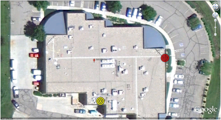
The observations used in this report were collected on the roof of the UNAVCO facility. The GNSS antenna test location is shown below with a red circle. The approximate location of the Iridium antenna bank is indicated with a yellow circle. The separation of the antennas is ~35 m.
GPS Data Processing
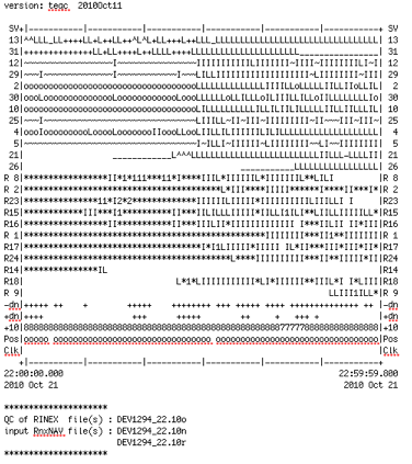
The GNSS data in this report were processed using TEQC. Leica files were translated from the Leica .m00 format to RINEX using TEQC. Trimble data must first be translated using the Trimble translator program runpkr00 before being translated to RINEX using TEQC. Navigation files were extracted from the data using the +nav flag. We used the +qc flag to quality check each RINEX file. For this report we only use the TEQC summary file with the .10S filename extension. We use two pieces of information from the summary file to detect possible iridium interference in our GNSS data, the “qc plot†and the obs/slip number.
All of the receivers in this report were set with 0 degree elevation mask. Both the number of sessions and the frequency of the data vary from receiver to receiver. Although, there were primarily 15 sec, 1 Hz and 5 Hz sessions recorded.
Results
Iridium Off vs. On
Iridium: Turned on at approximately 22:30:00
Receiver Type: Trimble NetR9
Antenna Type: Trimble GNSS Choke
Iridium: Was transmitting for the duration of this session
Receiver Type: Leica GR10
Antenna Type: Trimble Zephyr Geodetic 2 -> Trimble Zephyr Geodetic
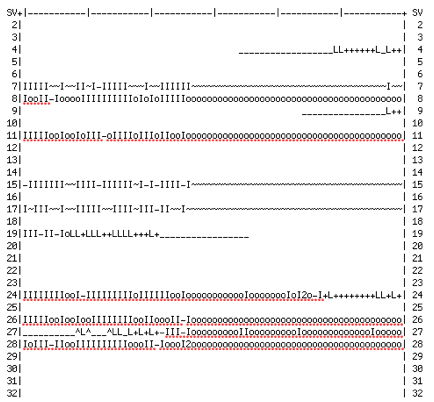
We tested several antenna models commonly used by UNAVCO to determine which are more susceptible to interference from Iridium signals. We observed a significant decrease in both loss of lock indicators (L) and ionospheric delay slip indicators (I) for tracked GPS satellites when we changed the antenna from a L5 and Galileo enabled Trimble Zephyr Geodetic 2 to the older Trimble Zephyr Geodetic antenna. This decrease occurred in recorded observables from both the GR10 and NetR9 receivers. Other antenna/receiver combinations were also tested and those tests are summarized in Table 1.
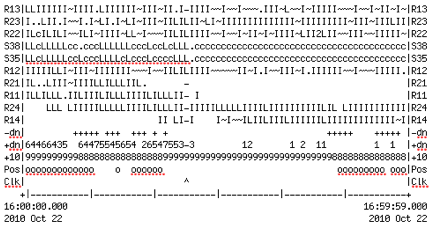
Loss of lock and ionospheric delay slip indicators in the
GLONASS observables did not decrease as significantly from the antenna change.
We suspect that the proximity of the GLONASS L1 frequency to the Iridium
frequency band makes it more susceptible to interference, even when using an older
narrower band antenna.
Conclusions
Summary Table
This table shows receiver/antenna combinations with known increased sensitivity to interference from Iridium Transmissions. A distance of 30 m between iridium and GNSS antennas with these combinations will not prevent the degradation of GNSS data.
Table 1.
|
|
Leica AR10 |
Trimble GNSS Choke TRM59800.00 |
Trimble Choke TRM29659.00 |
Trimble Zephyr Geodetic 2 TRM57971.00 |
Trimble Zephyr Geodetic TRM41249.00 |
|
Leica GR10 (Rev 2 board) |
Yes |
Yes |
|
Yes |
|
|
Trimble NetRS |
|
|
|
|
|
|
Trimble NetR8 |
|
|
|
|
|
|
Trimble NetR9 |
Yes |
Yes |
|
Yes |
|
[1] /questions/110/Iridium+%26+GPS+Antenna+Interference+Test+(2008)
Article ID: 675
Created: October 24, 2011
Last Updated: October 24, 2011
Author: Henry Berglund
Online URL: https://kb.unavco.org/article/iridium-gps-gnss-inteference-from-iridium-data-transmitters-675.html