
The Effects of L2C Signal Tracking on High-Precision Carrier Phase GPS Postioning
The Effects of L2C Signal Tracking on High-Precision Carrier Phase GPS Postioning
Introduction
In December, 2005, the L2C signal was introduced to improve the accuracy, tracking and redundancy of the GPS system for civilian users. The unencrypted L2C code can be tracked with civilian receivers without correlation. The L2C signal provides a 6-12 dB-Hz SNR improvement over L2P(Y) legacy signal, and a small improvement over L1 C/A-code, which allows for better tracking in marginal signal conditions. With the recent launches of the first block II-F satellites (SVN62/PRN25; SVN63/PRN01), there are 9 healthy satellites broadcasting L2C signals. Seven Block IIR-M satellites also broadcast the L2C signal.
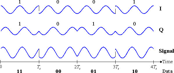
L2C is 90º out of phase with P2
The L2C signal is broadcast in quadrature (90º out of phase) with P2. For example, the two phase modulated carrier waves below (I and Q) are a cosine wave and a sine wave. The total signal or the sum of the two components is shown at the bottom. This quarternary modulation causes a quarter-cycle bias between the L2C and L2P phases. This bias is corrected by some some receivers (e.g. Ashtech, Septentrio, Trimble) and left uncorrected by others (e.g. Javad, Leica, Topcon).
Implications
How will the phase shifts affect carrier phase positioning?
- Depends on the make and model of your receiver
- Depends on the firmware version on your receiver
- Depends on how you have configured your receiver
- Depends on how you translate and pre-process your data
- Depends on how you process the positions
GNSS network operators such as the UNAVCO Plate Boundary Observatory (PBO) have been hesitant to use the new signal as it is not well determined how tracking and logging L2C could affect the positions derived from L2 carrier phase measurements for a given receiver. The L2C capability of receivers currently in widespread use in permanent networks can depend on firmware as well as hardware; in some cases receivers can simultaneously track L2C and L2P(Y) phases and some can track only one or the other, and the resulting observation files can depend on how individual operators configure the devices. Some data formats do not allow for both L2C and L2P phase measurements. Just because you’re tracking both L2 phases does not mean that you’re logging both!
Some known data formats that can not log both L2C and L2P phase measurements:
- Trimble Record Type 17 (RT17, e.g. an option on the NetRS receiver)
- Default Topcon TPS messages
- Binex Record 7f-03 (Leica and some Trimble Receivers)
Just as the knowledge of GPS P1-C1 biases is a must for successful ambiguity resolution (on long baselines), coping with receiver dependent 0.25-cycle phase biases between L2P and L2C will be a must before L2C can be used in GNSS analysis software.
Pre-processing
In cases where your RAW data contains both L2C and L2P, translation software (such as UNAVCO’s teqc) must be used carefully in order to select which L2 observation is written to RINEX and used in positioning. RINEX 2.XX currently allows for a single L2 phase and SNR observables (it does allow for multiple L2 psuedoranges). RINEX 2.13 is currently under development and will allow both phases and SNR observables. Modifications were made to teqc in early 2010 to eliminate potential confusion in that part of the process; if L2C code observations appear in a RINEX file produced by teqc, the L2 phase and S2 SNR observations were from the L2C carrier for those satellites.
An example using teqc to translate a Trimble .T02 file into RINEX obs and nav files:
(# indicates a comment; $$ indicates a command line prompt)
# List the raw T02 trimble file format $$ ls *.T02 5024K68287201110190000a.T02 # Use the Trimble utility "runpkr00" to unpack T02 file $$ runpkr00 -g -d *.T02 # List the newly created file $$ ls *.tgd 5024K68287201110190000a.tgd # Use teqc to translate the tgd file into RINEX obs and nav files $$ teqc +obs + +nav +,+ -tbin 1d NTR9 5024K68287201110190000a.tgd teqc: creating file ’NTR92920.11n’ ... teqc: creating file ’NTR92910.11g’ ... teqc: creating file ’NTR92910.11n’ ... teqc: creating file ’NTR92920.11o’ ... teqc: creating file ’NTR92920.11g’ ... teqc: creating file ’NTR92930.11n’ ... # The default translation of a tgd file does not include the C2 observable # The -O.sum . flag displays the type and number of observables for each satellite $$ teqc -O.sum . NTR92920.11o L1 L2 C1 P2 P1 S1 S2 ---- ---- ---- ---- ---- ---- ---- G18 927 914 927 914 0 927 914 G25 1127 1124 1127 1124 0 1127 1124 G16 1044 1022 1044 1022 0 1044 1022 G21 883 876 883 876 0 883 876 G29 950 943 950 943 0 950 943 ... ... # Adding the +C2 flag to the teqc command will include the C2 observable if present $$ teqc +C2 +obs + +nav +,+ -tbin 1d NTR9 5024K68287201110190000a.tgd teqc: creating file ’NTR92920.11n’ ... teqc: creating file ’NTR92910.11g’ ... teqc: creating file ’NTR92910.11n’ ... teqc: creating file ’NTR92920.11o’ ... teqc: creating file ’NTR92920.11g’ ... teqc: creating file ’NTR92930.11n’ ... # Check to see that C2 was written to the RINEX $$ teqc -O.sum . NTR92920.11o L1 L2 C1 C2 P1 S1 S2 P2 ---- ---- ---- ---- ---- ---- ---- ---- G18 927 914 927 0 0 927 914 914 G25 1127 1127 1127 1127 0 1127 1127 1124 G16 1044 1022 1044 0 0 1044 1022 1022 G21 883 876 883 0 0 883 876 876 ... ... # If we compare the observables from the newly created RINEX # obs files, we can see that L2 and S2 change when C2 is # included. # file with C2 8 L1 L2 C1 C2 P1 S1 S2 P2 #/TYPES OF OBSERV 128702420.712 6 100287619.952 6 24491243.219 24491258.852 41.500 41.400 24491257.961 # file without C2 7 L1 L2 C1 P2 P1 S1 S2 #/TYPES OF OBSERV 128702420.712 6 100287606.95643 24491243.219 24491257.961 41.500 23.000
To date L2C analyses have been restricted to special applications such as snow depth and soil moisture using SNR data (e.g. Larson et al., 2009; Larson et al., 2010).
How does using the L2C phase affect 24-hour baselines using TRACK?
It will depend on what receivers you use and if they correct for the 1/4 cycle phase difference between L2C and L2P.
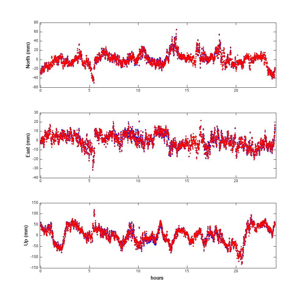
The following figure shows the difference between two TRACK analyses using (1) the L2P phase (blue) and (2) the L2C phase (red). Both receiver models corrected for the 1/4-cycle difference.
- Receiver 1 (quadrature corrected)
- Receiver 2 (quadrature corrected)
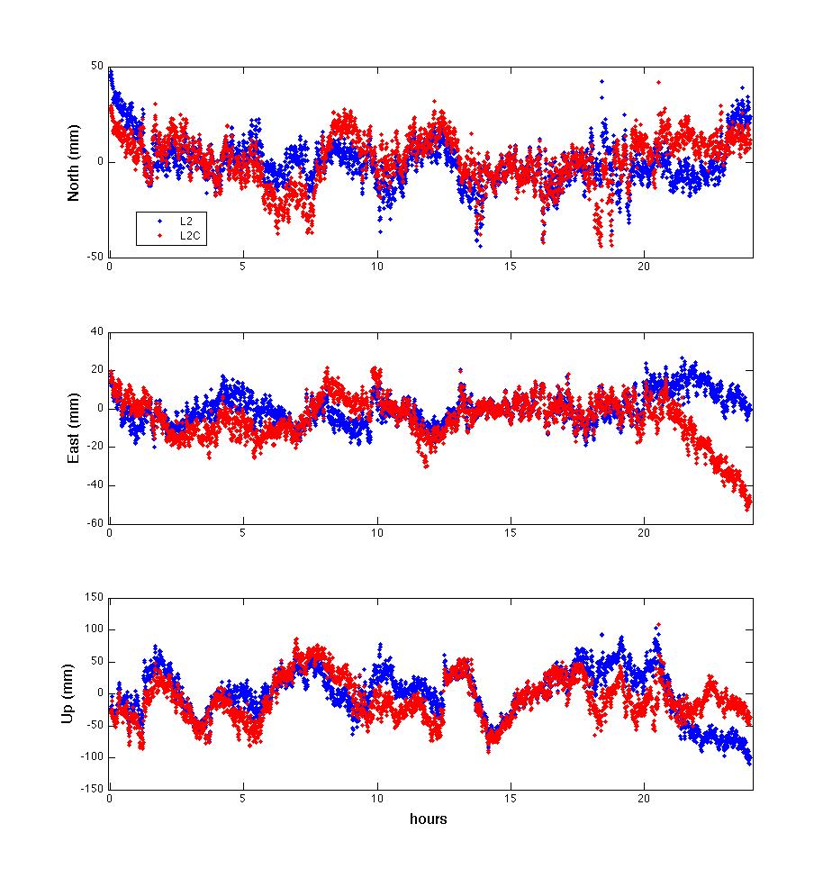
The following figure shows the difference between the L2P and L2C analyses when using one receiver that corrects for the 1/4-cycle bias and one receiver that does not. The uncorrected 1/4-phase bias in the L2C data from receiver 2 prevents TRACK from completely resolving all of the ambiguities, thereby degrading the position solution.
- Receiver 1 (quadrature corrected)
- Receiver 2 (no quadrature correction)
How does using the quadrature corrected L2C phase affect positioning (GAMIT/GLOBK)?
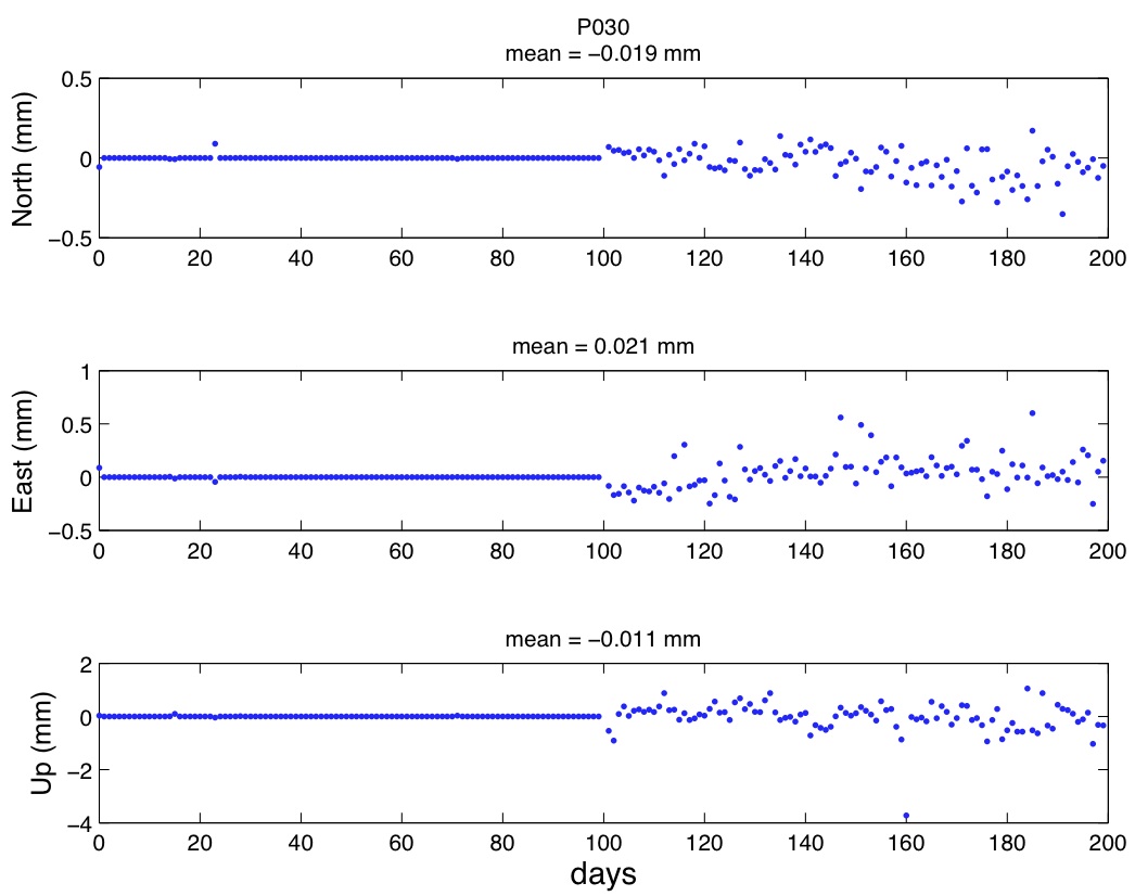
In the following example we compare two 200-day position time series from the site P030 (a linear trend was removed from each component for clarity). Tracking of both the L2P and the L2C phase observables was enabled at day 100. P030 is equipped with a Trimble NetRS receiver which corrects for the 1/4-phase bias. The two overlapping position time series below were estimated using the L2C observables when available (green) and with the standard L2P observables only (blue). We observed sub-millimeter differences in the estimated horizontal positions and differences < ~3 mm in the vertical.
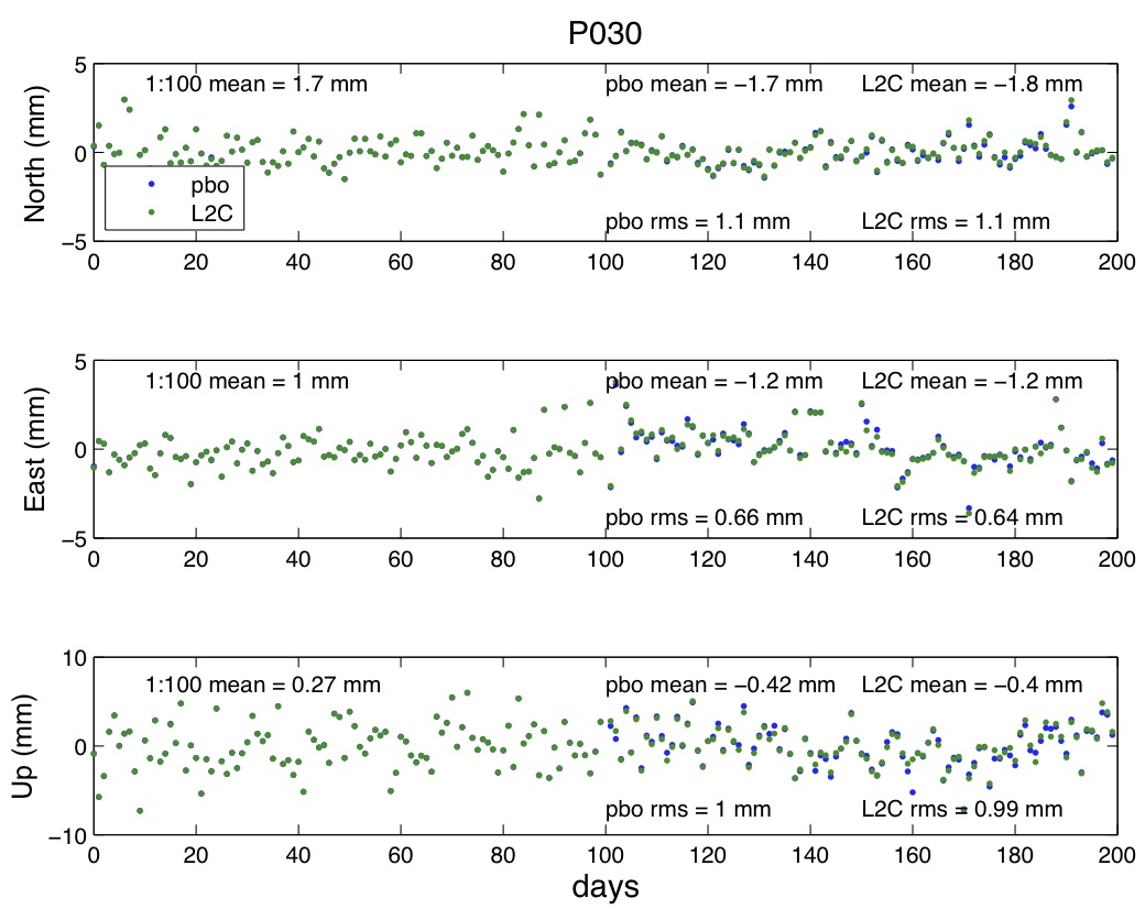
The mean differences between the position time series are < ~0.1 mm in the horizontal and < ~0.2 mm in the vertical components (shown below).
How does receiver tracking performance change when tracking L2C vs. L2P?
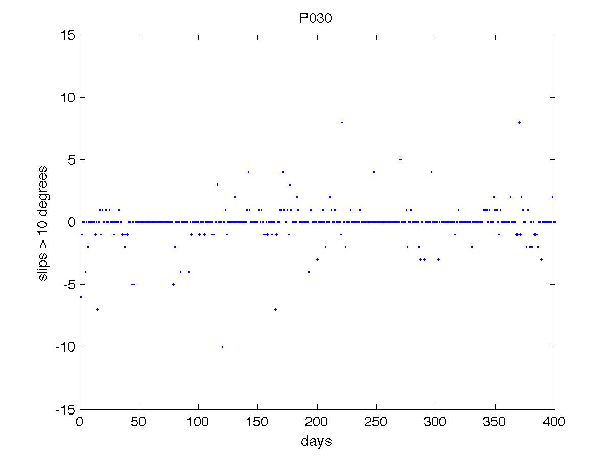
At site P030 we have observed that for elevation angles > 10º there is no significant change in the number of slips or the number of observations when comparing the L2P and L2C carrier phase measurements. The mean difference over this 400 day period is ~0.2 slips. The number of slips that occur in the L2C carrier phase measurements is slightly less or roughly equivalent to the number that occurred in the L2P(Y) measurements at this site.
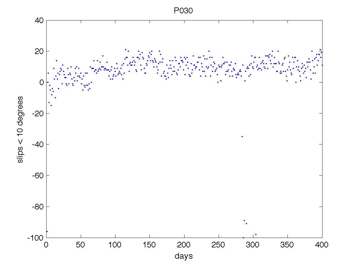
We have observed that for elevation angles < 10º the mean difference between the number of slips for L2C and L2P phases is ~7.7 slips over a 400 day period. Tracking L2C increases the number of observations, but it also increases the number of slips for elevation angles < 10º.
Direct comparisons of the L2 and L2C phase observables
Receivers use separate correlators or channels for each L2 carrier phase measurement. Differencing the L2 and L2C carrier phase measurements allows us to investigate the instrument’s semi-independent measurement noise and reveals the receiver’s digitizing resolution (the banding). The figure below shows the direct comparison of the L2 phase observable from two RINEX (2.11) files separately translated from the same receiver (Trimble NetRS) over the same time period. The change in cycles between each epoch for the L2 and L2C observables is differenced and plotted with respect to time (hours). We used teqc to translate the RT27 data file into two RINEX files: 1) a file that included the L2C phase observable, 2) a file that excluded the L2C phase observable. The L2 and L2C observables show sub-millicycle differences over a 24-hour mean with variations up to ~±0.06 cycles.
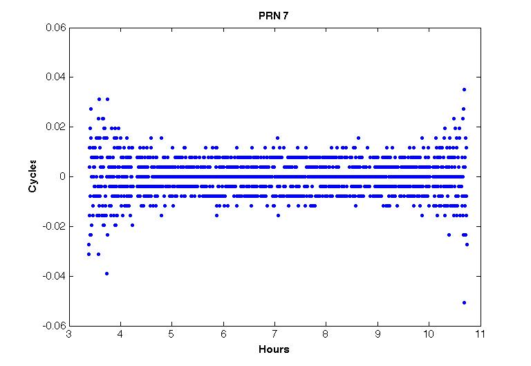
The difference between each band in the figure above is ~0.0039 (1/256) cycles. This banding demonstrates that the digitizing resolution of the NetRS receiver is 1/256 (1/2^8) of a cycle - implying that the receiver is using an 8 bit A-D conversion. The analysis above was done using a translation of RT27-format data using extended resolution on the phase values beyond the usual 0.001 cycle resolution available in RINEX observation format.
Summary and Conclusion
-
The receiver dependent 1/4-phase bias in L2C measurements needs to be accounted for before L2C is suitable for use in carrier-phase positioning.
-
Currently, processing networks with mixed receiver brands and L2C enabled can lead to poor positioning results.
-
L2C complicates receiver configuration choices and pre-processing. Improper receiver configuration and/or pre-processing can result in loss of L2P phase information and missing observations. Development of RINEX 2.13 will help to reduce the complexity of pre-processing data formats which include L2C phase information.
- IGS and RTCM should encourage universal quadrature corrections for the L2C phase observables. Otherwise, the receiver dependent quadrature correction will need to be known before estimating position.
-
It is unknown what phase measurements are output in real-time streams when L2C is enabled. If L2C phase observables are present in real-time streams it may present a serious challenge to account for them in real-time applications.
-
IGS should specify that L2C phase not be used in "production" RINEX files used for position time-series
-
If both L2P and L2C phase must be logged, then use separate pre-processing flows for positioning (L2P) and special uses (L2C).