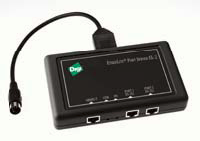
Digi Etherlite - How to configure the Digi EtherLite for data transfer
How to configure the Digi EtherLite for data transfer
An EtherLite with firmware version of 1.X is referred to a "Digi RealPort". This Document refers to Firmware version 1.2.

Cabling
The EtherLite utilizes an RJ45 to DB9 converter which is not supplied with the unit. The following table can be used to build one:
RJ45 DB9 1 7 2 6 3 1 4 2 5 3 6 5 7 4 8 8 -
Configuring the device
Use this procedure to permanently store an IP address in an EtherLite module using Boot Console. Boot Console can also assign subnet mask and a gateway address.
Boot console commands:
|
Command |
Command Description |
| help | Displays the command list with a brief description |
| show | Shows all settings |
| boot | Resumes the boot process with status messages being logged to the terminal |
| ip | Sets the IP address (The default address is 0.0.0.0) |
| gw | Sets the gateway address (The default address is 0.0.0.0) |
| sm | Sets the subnet mask address (The default address is 255.255.0.0) |
| ahip | Sets the authorized hosts IP address This specifies which DHCP server can assign an IP address to an EtherLite module. (The default address is 0.0.0.0) |
| ahm | Sets the authorized hosts mask address (The default address is 0.0.0.0) |
| tftpip | Sets the server host for bootfile tftp address (The default address is 0.0.0.0)* |
| bf | Sets the bootfile name (The default name is elxx.prm)* |
| store | Stores the settings in flash RAM |
| erase | Erases the settings in flash RAM and resets all the defaults |
| reset | Resets all defaults |
| ping | Pings an IP address |
| * Note: These values are not supported by the store command, consequently when the EtherLite module loses power this information will be lost. |
Procedure
Attach a terminal or terminal emulator to Port 1 of the EtherLite module.
Attach a 3-wire connection: Txd, Rxd, and Gnd. (Use a straight Ethernet cable, the RJ45 to DB9 converter above and a DB9 null modem.
Open a Windows HyperTerminal (or use Linux) - Note: EtherLite will not assert DTR or RTS. If your system is expecting these signals, loop them at the terminal side. Boot Console operates at 19200 baud, 8 bits, 1 stop, and no parity.
Activate the console by removing the Ethernet cable and unplugging the power cable.
Plug the power cable back into the EtherLite module.
Repeatedly depress the # key at the terminal until you get a console prompt. - It should only take three keystrokes.
A prompt will appear with the module model and the firmware version. An example would be: --EL-32 V6.8-- ?
Enter the IP address by entering the command ip x.x.x.x
(Where x.x.x.x is the actual numerical address.)
Enter the command: store - This command stores the IP address in flash memory.
Reboot the EtherLite module by unplugging, and then plugging in the power cable again. - Note: The EtherLite module should remain off for at least 10 seconds before powering the unit back on again.
Verify the network presence of the EtherLite module by connecting the 10BaseT port to the internet and using Ping from a terminal window of the PC.
Install Linux Drivers
Download the latest RealPort software from the Digi web site: http://www.digi.com/support/productdetl.jsp?pid=3037&osvid=0&s=261&tp=1
Currently, that file is: 4002086.src.rpm
rpm -ivv 4002086.src.rpm (prepare for installation)
cd /usr/src/redhat/SPECS
rpm -bb --target=<arch> realport-1.3.spec (perform make and install AND make binary rpm)
cd /usr/src/redhat/RPMS/<arch>
rpm -ivv realport-1.3-0.<arch>.rpm (install the package)
For Linux 7.x, create the following symbolic links
ln -s /usr/src/linux-[kernel version] /usr/src/linux
ln -s /usr/bin/dgrp/dgrp.o /lib/modules/`uname -r`/misc/dgrp.o.
Configure the Linux device driver
Run the command /usr/bin/dgrp/config/dgrp_gui. This will bring up a GUI interface which allows Digi RealPorts to be added to the host system.
Press Add
RealPort ID: The name of the device to be added, this can be up to 2 numbers or letters (they myst be unique to the system. For example, if the ID chosen were jj then the first port of the new device would be /dev/ttyjj00 and the 2nd would be /dev/ttyjj01.
IP Address or name: The IP address entered into the Unit above.
Number of Ports: 2 for the EL2
All other fields can be left to the default value provided.
Press Commit – another screen will appear, press Run it. (These should be no errors)
Press Exit when the process completes. The new devices are now available for use by any program which uses a com port. Type ls /dev/ttyjj* and you will see the two new devices.
)