Location: UNAVCO facility roof NE corner
Author: Henry Berglund
Contact: Berglund@unavco.org
Introduction:
Trimble currently offers two choke ring antenna designs for GNSS applications:
-
The Trimble GNSS Choke Ring Antenna has a traditional Dorne Margolin element with an updated LNA. The new LNA improves tracking of new GNSS signals by increasing the width of amplified bands. The choke ring ground plane design has not been altered from the TRM29659.00 design.
- The Trimble GNSS Ti Choke Ring Antenna shares the same choke ring ground plane as the TRM29659.00 and the TRM59800.00 antennas, but has a newly designed element that was borrowed from Trimble’s GNSS Zephyr antenna. The new element significantly reduces the cost of the antenna, thereby making it an attractive low-cost alternative to many Dorne Margolin designs.
The UNAVCO community has started to show interest in substituting use of the TRM59800.00 with the TRM59900.00 due to the significantly reduced cost of the GNSS Ti Choke Ring design. This report provides an antenna performance comparison. All of the tests included in this report were conducted on the roof of the UNAVCO facility, located in Boulder, CO. For the majority of testing, each antenna was installed on the same monument for a multi-day occupation at a similar time of year. No precipitation was recorded during either occupation. A Trimble NetR8 receiver was used to record GPS C1,C2,P2,L1,L2,S1,S2 signals and GLONASS C1,C2,P1,L1,S1 signals at 30 second intervals. The results will be outlined in the following sections of this report.
- SNR Comparison
- Teqc QC Results
- MP1 and MP2
- Power Consumption
- Near-Field Sensitivity
- Phase Center Calibrations
SNR Comparison
The following Teqc QC output shows the mean S1 and S2 values on days 151 and 152 for both the TRM59900.00 antenna (TICR) and the TRM59800.00 antenna (DMCR). The TRM59900.00 shows ~3% lower mean S1 and ~10% lower mean S2.
DMCR1510.12S:Mean S1 S2 : 46.72 (sd=4.60 n=25537) 34.85 (sd=8.10 n=25535)
DMCR1520.12S:Mean S1 S2 : 46.80 (sd=4.59 n=25530) 35.04 (sd=8.08 n=25528)
TICR1510.12S:Mean S1 S2 : 45.00 (sd=4.65 n=25537) 31.33 (sd=8.44 n=25523)
TICR1520.12S:Mean S1 S2 : 45.09 (sd=4.64 n=25530) 31.50 (sd=8.44 n=25526)
To compare the antennas SNR performance as a function of elevation angle we have plotted 4-day SNR averages in 5-degree elevation bins. The SNR measurements were parsed from Teqc COMPACT2 format files. Figure 1 shows the average S1 and S2 values for both antenna design.
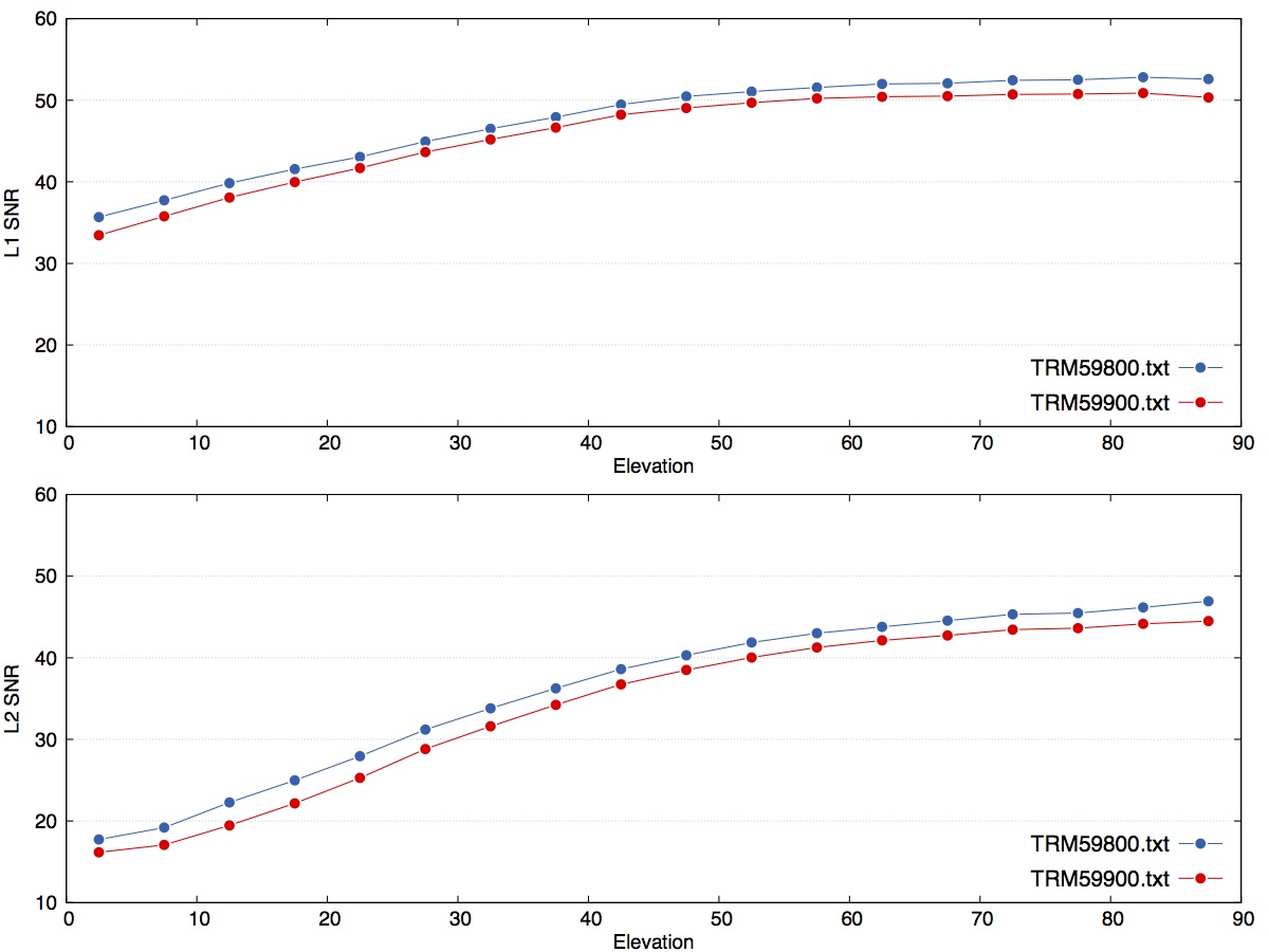
Figure 1. L1 and L2 SNR average values binned in 5-degree increments. Trimble GNSS Choke antenna (TRM59800.00) is shown in blue. Trimble GNSS Ti Choke (TRM59900.00) antenna is shown in red.
Teqc QC Results
By grep’ing the SUM line from the Teqc QC output files we can show that on 2012, day 151 the TRM59900.00 had two slips above 10 degrees, while the TRM59800.00 had none. The total number of observations for the TRM59900.00 antenna was 12 fewer for day 151 and 2 fewer for day 152. The differences in both in the number of observations and the number of slips above 10 degrees are small and possibly insignificant. Side-by-side outdoor testing requires that the antennas occupy different monuments and use separate receivers for data acquisition. It is likely that small changes in antenna position, cables, and receiver could cause variations in tracking performance that are unrelated to the antennas performance. Long-term testing or the use of a controlled RF environment could be used to reduce test setup error. The output below shows the QC summary lines output by Teqc.
first epoch last epoch hrs dt #expt #have % mp1 mp2 o/slps
DMCR1510.12S:SUM 12 5 30 00:00 12 5 30 23:59 24.00 30 25537 25535 100 0.50 0.39 25535
DMCR1520.12S:SUM 12 5 31 00:00 12 5 31 23:59 24.00 30 25530 25528 100 0.50 0.38 25528
TICR1510.12S:SUM 12 5 30 00:00 12 5 30 23:59 24.00 30 25537 25523 100 0.49 0.39 6381
TICR1520.12S:SUM 12 5 31 00:00 12 5 31 23:59 24.00 30 25530 25526 100 0.51 0.41 25526
Bt grep’ing the slips below the 10 degree elevation mask we can show that for the TRM59900.00 antenna more slips occurred below 10 degrees elevation on both test days.
DMCR1510.12S:IOD slips < 10.0 deg* : 30
DMCR1520.12S:IOD slips < 10.0 deg* : 30
TICR1510.12S:IOD slips < 10.0 deg* : 36
TICR1520.12S:IOD slips < 10.0 deg* : 35
MP1 and MP2
MP1 is a linear combination of P1, L1 and L2, MP2 is a linear combination of P2, L1, and L2. The MP1 and MP2 combinations reflect multipath plus receiver noise. Using the values computed by Teqc we plotted MP1 and MP2 with respect to satellite elevation angle for each antenna. The scatter of the MP1 and MP2 values reflects the magnitude of multipath plus receiver noise in the data. Receiver and multipath noise are both known to increase as satellite elevation angle decreases. The results shown in Figures 2 and 3 demonstrate that MP1 and MP2 scatter does increase as satellite elevation angle decreases.
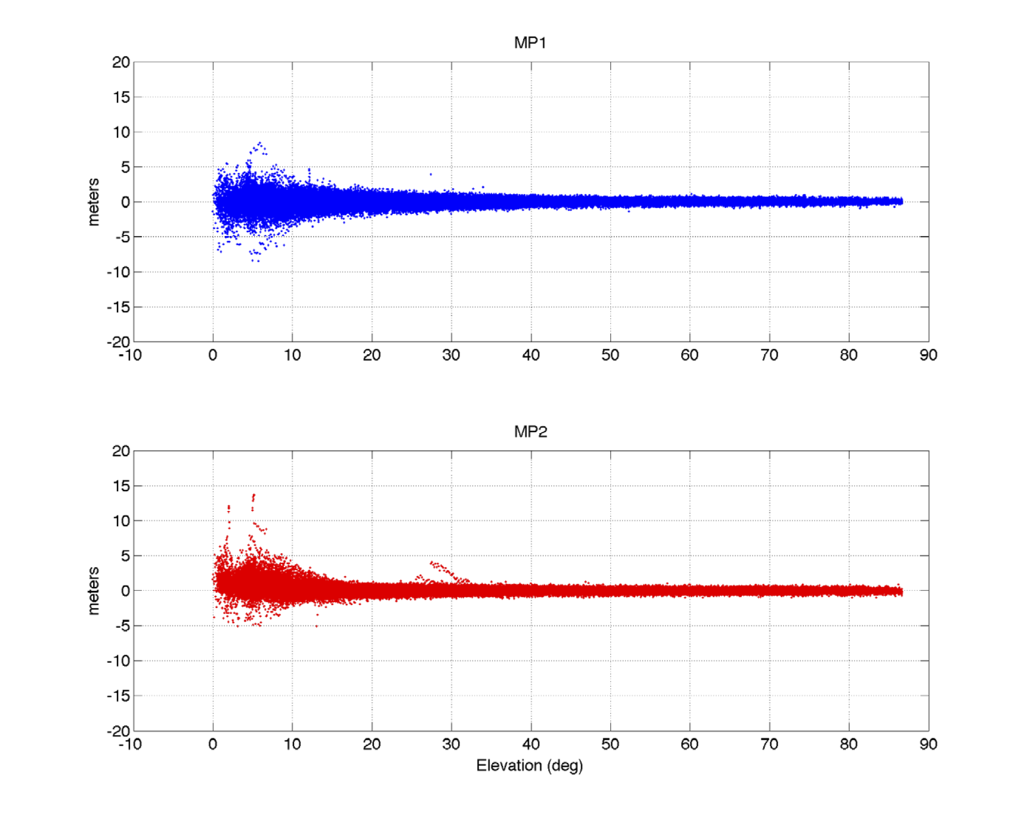
Figure 2. TRM59800.00 (blue) and MP2 (red) plotted with respect to elevation angle. The values were collected over a period of four days.
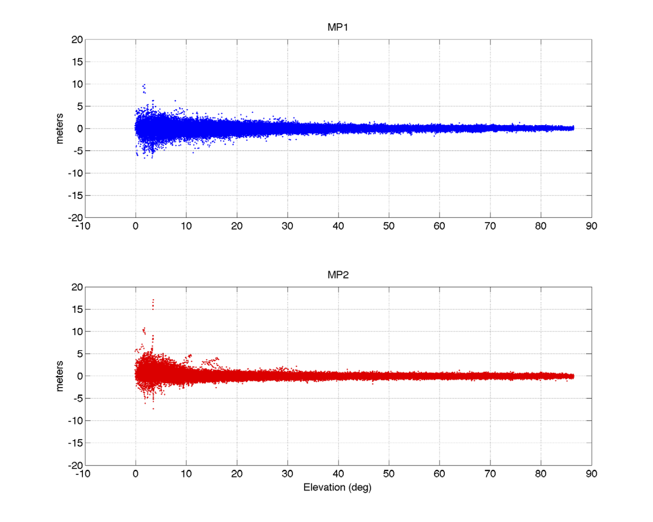
Figure 3. TRM59900.00 MP1 (blue) and MP2 (red) plotted with respect to elevation angle. The values were collected over a period of four days.
To quantify the difference between the multipath and receiver noise from both antennas we can compare the RMS of the MP1 and MP2 linear combinations. Figures 4 and 5 show 4-day MP1 and MP2 RMS averages calculated over 5-degree elevation bins. We can see from these figures that the TRM59900.00 antenna has slightly lower MP1 and MP2 RMS at high elevations, but it has slightly higher MP1 and MP2 RMS at low elevations.
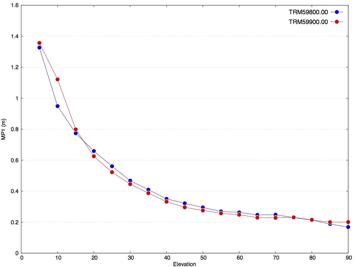
Figure 4. Binned 4-day average MP1 RMS.
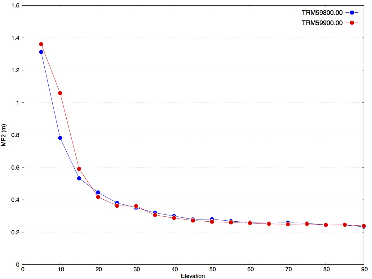
Figure 5. Binned 4-day average MP2 RMS.
Power Consumption
Power consumption of the antennas is an important parameter, especially for remote sites located in challenging solar environments. The power needs for the following Trimble antenna models were measured using an Agilent N6705 DC power analyzer. Power consumption measurements were taken at two common voltage biases. Table 1 shows the results from our test. The TRM59900.00 antenna uses ~12% and ~6% less power than the TRM59800.00 at 7V and 5V, respectively.
|
Make |
Model |
Bias 1 |
Power 1 |
Bias 2 |
Power 2 |
|
Trimble |
TRM29659-00 |
7.0V |
0.414 W |
5.0V |
0.265 W |
|
Trimble |
TRM39105.00 |
7.0V |
0.737 W |
5.0V |
0.523 W |
|
Trimble |
TRM41249.00 |
7.0V |
0.712 W |
5.0V |
0.506 W |
|
Trimble |
TRM57971.00 |
7.0V |
0.633 W |
5.0V |
0.436 W |
|
Trimble |
TRM59800-80 |
7.0V |
0.712 W |
5.0V |
0.48 W |
|
Trimble |
TRM59900-00 |
7.0V |
0.624 W |
5.0V |
0.448 W |
Table 1. Tabulated Power measurements for common Trimble antenna models.
Near-Field Sensitivity
To understand how near-field multipath may impact position estimate accuracy, we developed a new antenna mount where the near-field environment could be altered without moving the antenna.
For the results in Table 2 we used only the two uppermost notches on our test standoff. Approximately a week of observations were collected with the plate in the uppermost position. After a week, the plate was moved from the uppermost notch to the middle notch for an additional week of data collection. The antenna was never displaced during testing. A single reference antenna, located ~1m from the test antenna, was used throughout the experiment to provide a short baseline for post-processing.
After the data were collected, the GAMIT/GLOBK software package was used for post-processing and analysis. A small regional network of 7 sites, 5 regional sites and 2 test sites, were processed together. A priori coordinates and velocities (ITRF2008) for the 5 regional sites were used to establish a stable frame of reference. Estimated coordinates for the test antenna and the reference antenna were then differenced to determine daily baseline estimates in a NEU coordinate system. Weighted least squares were used to estimate the offset that occurred in each component after the plate had been adjusted. The resulting offset estimates for each tested antenna type are shown in Table 2 with their respective formal uncertainties.
A more detailed report of the experiment is available at the following link:
|
Antenna Type |
North |
East |
Up |
|
SEPCHOKE |
0.3 +− 0.2 mm |
0.2 +− 0.2 mm |
-2.7 +− 2.1 mm |
|
TPSCR.G3 |
0.4 +− 0.1 mm |
0.0 +− 0.1 mm |
2.1 +− 1.3 mm |
|
TPSPG_A1+GP |
-1.4 +− 0.2 mm |
3.8 +− 0.2 mm |
-4.5 +− 2.2 mm |
|
TRM41249 |
-0.3 +− 0.2 mm |
-0.3 +− 0.2 mm |
0.3 +− 2.2 mm |
|
TRM57971 |
0.5 +− 0.4 mm |
0.4 +− 0.4 mm |
-2.9 +− 3.2 mm |
|
TRM59800 |
-0.2 +− 0.4 mm |
-0.5 +− 0.4 mm |
-0.2 +− 3.4 mm |
|
TRM59900 |
-0.2 +− 0.4 mm |
-0.4 +− 0.4 mm |
-0.2 +− 3.3 mm |
Table 2. Tabulated offset estimates for north, east and up components.
These results show that both the TRM59800.00 and TRM59900.00 type antennas are relatively insensitive to changes in the near-field environment making them a good choice for geodetic applications where stable phase centers are critical.
Phase Center Calibrations
Robot calibrations are currently available in the IGS ANTEX format for the following antenna codes:
Antenna Type Radome By
TRM59900.00 NONE IfE, Univ. Hannover
TRM59900.00 SCIS IfE, Univ. Hannover
TRM59800.00 NONE Geo++ GmbH
TRM59800.00 SCIS Geo++ GmbH
TRM59800.00 SCIT Geo++ GmbH
SCIS denotes SCIGN short radome
SCIT denotes SCIGN tall radome
NONE denotes no radome
Summary
We have characterized several performance aspects of two GPS antennas using data collected on the roof of our facility. Our results show that the new TRM59900.00 antenna compares favorably with the older Dorne Margolin design (TRM59800.00) while costing significantly less. The newer TRM59900.00 antenna uses the field proven element from the Trimble Geodetic Zephyr antenna but keeps the same choke ring ground plane used in TRM59800.00. The TRM59900.00 tracked L1 and L2 with ~3% and ~10% lower SNR, respectively. Despite the lower measured SNR for L1 and L2, performance as measured by the number of complete observations and slips did not decrease significantly. We did not investigate how lower SNR on L2 may impact GPS multipath reflectometry results.
If you would like access to the data that was used for this analysis please contact Henry Berglund at: Berglund@unavco.org