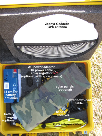
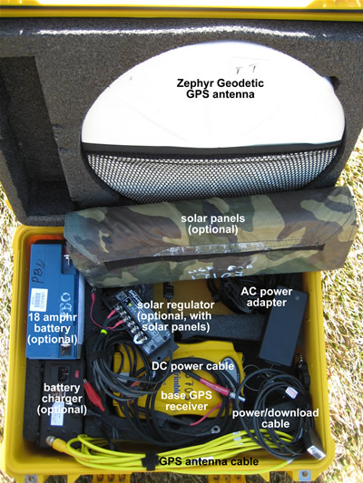
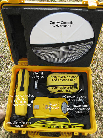
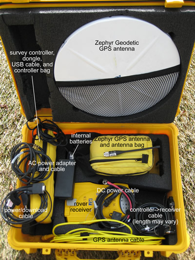
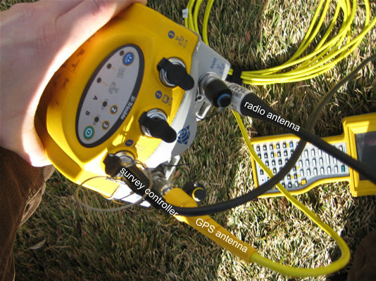
UNAVCO NSF EAR RTK base GPS unit: typical packing (left) and view of all components (right).
Real-time kinematic (RTK) surveys provide centimeter-level precision coordinates without post-processing. RTK surveys are generally used for mapping or for surveying points where only several cm of precision are needed, such as 1) mapping out a feature such as a falt scarp or a shoreline; 2) recording the locations of sample sites; or 3) measuring the positions of markers such as stakes on a glacier to determince ice velocities. Occupation times for survey points are on the order of seconds. Because the measurements are real-time, not requiring post-processing of the data, RTK is also a strong navigational tool, allowing the user to navigate to within 1.5 cm of a target, e.g. an unmarked sample site such as a plant that the researcher would like to revisit. RTK requires use of radios to communicate corrections in real-time. This adds a level of complexity to the survey and is often not recommended unless the real-time capabilities are specifically needed. Otherwise, consider executing a post-processing kinematic survey instead.
RTK surveys require operation of at least two receivers: a ‘base’ receiver, sending correctional information, and one or more ‘rover’ receivers receiving correctional information and surveying or navigating to points. You may use as many rover receivers as you wish. If you have access to real-time data transmissions from a reference station already operating in your area (within several km and approximate line-of-site of your survey), there may be no need to set up an additional base station.
There are three types of survey methods in RTK surveys: topo points, continuous surveys, and stakeouts. Topo points are short (usually 3-15 second) occupations, e.g. over a sample site or survey marker. Continuous survey mode allows ongoing data collection at a specified logging interval, e.g. every 5 seconds, or a specified distance interval, e.g. 1 meter. Continuous mode is used for mapping. Stakeout mode allows navigation to predetermined coordinates.
Geography. The base station should be located within several (approximately 5) km of and in approximate line of site of the area to be surveyed. Radio links and corrections may not work over longer distances or in situations of poor visibility between the base radio and the rover radio(s). Consider locating your base in an open area from which you can see your entire survey area. Repeater radios can be used to relay the base corrections to the rover(s) in variable terrain. If you think you may lose line-of-sight communication between the base and the rover(s), conduct an ’rtk and infill’ survey (described below).
Base. The base GPS antenna can be set up over an existing mark or a newly established mark, or, if no repeat surveying will be needed, placed directly on the ground. Correspondingly, the antenna mount used (if any) will depend on project needs. For a repeatable survey, you will need a way to center and level the antenna over your mark. If you are setting up over a known mark (preferred), it is best to know the coordinates of the mark beforehand. You will have to give the base station its coordinates in WGS-84 latitude, longitude, and height when you start the survey. If you do not know the coordinates of the base station but can obtain them (e.g. by collecting data during your survey and processing the data for a point position later), you can adjust the survey accordingly in the lab after data collection. If you will be collecting data at the base station to obtain a base position, plan to collect at least an hour’s worth of data. See the UNAVCO Knowledgebase for more information on mounts (/questions/394/).
Coordinate system. Unlike for post-processing kinematic surveys, you are recommended to choose a projection and datum. If you are referencing a previous survey, you MUST use the same projection and datum that was used before. Record the projection and datum used for future surveys. If you are starting from scratch, consider using the universal transverse mercator (UTM) coordinate system; determine your zone by checking e.g. http://www.dmap.co.uk/utmworld.htm.
Data logging. Data are stored in the survey controller as coordinates; no raw data are stored unless specified. If you want to process the data after the survey, you must collect data at both the base receiver and at the rover(s). If this is the case, choose a logging interval before starting the survey. The base receiver must have a logging interval at least as high as the rover receiver’s; data from the rover can only be processed if corresponding data are collected at the base. The logging interval will depend on the survey goals. If mapping, think about how often you need a data point. For example, if doing a detailed survey or surveying from a vehicle, a 1 Hz (1 second) logging interval may be appropriate. For less detailed work and/or if walking, a 5 second logging interval may be appropriate.
Things to know before and during the survey:
Base GPS antenna type: _____________ (usually Zephyr Geodetic)
Rover GPS antenna type: _____________ (usually Zephyr or Zephyr Geodetic)
Base GPS antenna height measurement method: _____________ (usually "Bottom (or Top) of notch" or "Bottom of antenna mount")
Rover GPS antenna height measurement method: _____________ (usally "Bottom of antenna mount")
Base station coordinates: _____________ N/S latitude, _____________ E/W longitude, _____________ height (meters)
A survey controller is needed for running the rover receiver. The survey controller gives control over the survey and records metadata that facilitates data organization. Note that the TSC1 survey controller will not work with the R7 receiver.
The menu system is very similar for the Trimble TSC1, TSCe, and TSC2. There may be some slight variations in wording from what is shown here, depending on which controller you are using, but the general flow should be the same.
Navigation is also similar between controllers, although the TSC1 has no stylis or touch-screen and the TSCe and TSC2 do. Drop-down menus are indicated by a right-pointing arrow inside a circle. To see a drop-down menu in the TSC1, highlight the menu item and push the right arrow on the controller; in the TSCe and TSC2, touch the arrow. To go back a screen, press the "Esc" key (TSC1) or option (TSCe, TSC2). To get to the main menu, press the "Menu" key or option.
Each survey controller is powered by a removable battery; however, when plugged into a receiver the controller will run off the receiver’s power.
To save time in the field, configure your survey in the survey controller beforehand.
Turn on the survey controller by pushing the green power button.
If needed, enter the "Survey Controller" program by double-clicking the corresponding icon.
The main menu consists of 6 options on the screen. Select "Files" in the top left.
In the TSC1, select "Job management", then "New" (F1 key). In the TSCe, select "New Job".
Give the job a name using the letter and number keys and hit "Enter". In the TSC1, select a memory location for the job; suggested setting is Main memory. Hit OK (F1).
Select "Coordinate system" (in the TSCe and TSC2, double-click on it or highlight it and press the enter (arrow) key):
TSC1 only: If the job file for the previous survey is in your survey controller, select "Copy from other job". Select the job from the list.
If you are starting from scratch, we recommend you select "Select from library". Recommended settings are System: UTM, Zone: [determine your zone by checking e.g. http://www.apsalin.com/utm-zone-finder.aspx], Datum: WGS 1984, Use geoid model: No, Use datum grid: No, Project height: [approximate average survey elevation], Coordinates: Grid.
For a custom coordinate system for your survey, select "Key in parameters".
From the main menu, select "Configuration" in the top right.
Select "Survey Styles"-->"RTK" (or "RTK & infill" to collect raw data, options denoted by * asterisks *)-->"Rover options".
Survey type: RTK or RTK & infill
* Logging device: [Choose Controller or Receiver; suggested setting is Controller] *
* Auto file names: [Choose Yes or No; suggested setting is Yes] *
* Logging interval: [Choose logging interval; depends on survey goals] *
Broadcast format: [MUST be the same as the Broadcast format in Base options; suggested setting is CMR+; this refers to the format in which the RTK corrections are sent from the base]
WAAS: Off
INS position: RTK only (TSC1)
Use station index: [Must match Station index in Base options; suggested setting is Any if there are no other broadcasting RTK base stations in the vicinity (available only in some controllers--otherwise enter 29]
Prompt for station index: Yes
Satellite differential: Off (TSCe)
Elevation mask: [Enter elevation mask; suggested setting is 13 00’00"; this is the elevation angle from the horizon below which no data will be collected from satellites]
PDOP mask: [Enter PDOP mask; default setting is 6.0 but should be set higher in difficult surveying conditions (limited sky view); this is a quantitative expression of satellite geometry, with lower numbers representing more favorable geometries]
Antenna height: [Enter antenna height if known--can be modified in the processing or in the field]
Type: [Select antenna type from list]
Meas. to: [Select antenna height measurement method]
Serial number: [Enter antenna serial number, if known]
Hit Enter or Accept when done to get back to the RTK menu.
Select "Rover radio".
Type: [Select rover radio type from list. If using UNAVCO OPP equipment, select "Pacific Crest". If using UNAVCO EAR equipment, select "Trimble internal". If you select "Trimble internal," you are done with this page on a TSC1; select "Trimble 450/900" for "Method" on the TSCe.]
Route through controller: Leave blank (TSCe)
Controller port: [Select the port on the controller that you will be using to connect the controller to the rover receiver]
Receiver port: [Select the port on the receiver that you will be using to connect the rover receiver to the radio, usually port 3]
Hit Enter or Accept when done to get back to the RTK menu.
Select "Base options".
Survey type: RTK or RTK & infill
* Logging device: [Receiver] *
* Auto file names: [Yes] *
* Logging interval: [Select logging interal; must be at least as frequent as rover, e.g. 5 seconds] *
Broadcast format: [MUST be the same as the Broadcast format in Rover options; suggested setting is CMR+; this refers to the format in which the RTK corrections are sent from the base]
Output additional code RTCM: [No/blank]
Station index: [Must match Use station index in Rover options; suggested setting is 29]
Elevation mask: [Enter elevation mask; suggested setting is 13 00’00"]
Antenna height: [Enter antenna height--can be modified in the processing if necessary]
Type: [Select antenna type from list]
Meas. to: [Select antenna height measurement method]
Serial number: [Enter antenna serial number, if known]
Hit Enter or Accept when done to get back to the RTK menu.
Select "Base radio".
Type: [Select base radio type from list. If using UNAVCO OPP equipment, select "Pacific Crest". If using UNAVCO EAR equipment, select "TRIMMARK 3"]
Controller port: [Select the port on the controller that you will be using to connect the controller to the base receiver, usually COM1]
Receiver port: [Select the port on the receiver that you will be using to connect the rover receiver to the radio, usually Port 3]
Hit Enter or Accept when done to get back to the RTK menu.
Select "Topo point"
Auto point step size: [Enter auto point step size; suggested setting is 1; this automatically names points measured with the last character being a number 1 higher than that of the previous point measured]
Quality control: [Select quality control option; suggested setting is QC1&QC2]
Auto store point: [Select Yes or No; suggested setting is Yes; this automatically stores a point after the minimum conditions specified below are met]
Occupation time: [Enter minimum occupation time; suggested setting is 0m 5s; this specifies how long you would like to occupy a survey point]
Number of measurements: [Enter minimum number of measurements; suggested setting is 3; this specifies how many measurements you would like to collect before the controller stores your survey point]
Horizontal precision: [Enter minimum horizontal precision needed to store a measurement; suggested setting is 0.015m]
Vertical precision: [Enter minimum horizontal precision needed to store a measurement; suggested setting is 0.020m]
Hit Enter or Accept when done to get back to the RTK menu.
Press the Menu key to get back to the main menu. You are done configuring your survey.
If you are using a 5700 or R7 receiver, make sure there is a compact flash card in the receiver and enough memory for your survey (base station).
Make sure there is enough memory on your survey controller for your survey. If using a TSC1, make sure there is a compact flash or PCMCIA card in the controller.
Charge batteries. If using internal batteries, charge them in the receiver by plugging the receiver into an AC outlet using the AC power cable.
UNAVCO NSF EAR RTK base GPS unit: typical packing (left) and view of all components (right).
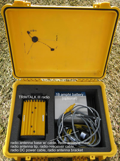
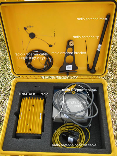
UNAVCO NSF EAR RTK base radio unit: typical packing (left) and view of all components (right).
UNAVCO NSF EAR RTK rover GPS unit: typical packing (left) and view of all components (right).
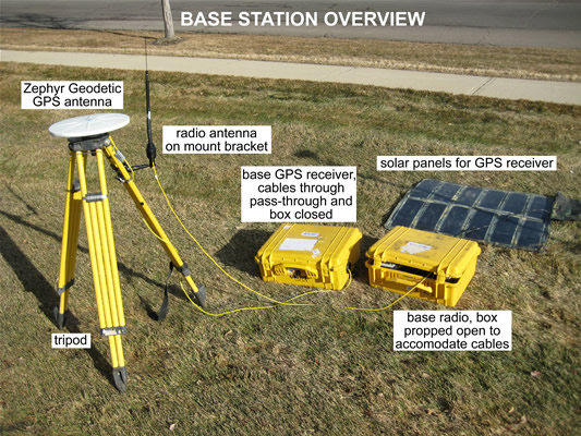
Base station setup may vary depending on the project goals. The suggested setup includes a high-precision (stable, centered, and level) and repeatable antenna setup. Antenna setup instructions will depend on the mount used. (See Base, under Planning the Survey, above.) The base station should have good sky view; it must track at least 5 satellites in common with the rover at all times.
The base must be operating at all times when the rover is running in order to attain corrected positions; set up the base station before starting the rover.
Set up the GPS antenna:
Level antenna mount where needed. Make sure the mount is centered over the mark.
Attach antenna to mount.
Align the antenna to true north where needed.
Measure and record the antenna height and the antenna height measurement method.
Attach the antenna cable to the antenna, if you haven’t already. Use the 90 degree connector for the antenna; pass the straight connector through the pass-through in the equipment case. DO NOT kink the cables; they are expensive, important, and subject to damage.
Connect the radio antenna to an antenna mount. The radio antenna should be aligned vertically.
Connect the radio antenna cable to the base radio.
Connect the base radio to an external battery. Make sure the radio antenna is connected to the radio BEFORE you connect the radio to power; the radio will power up automatically.
Connect the base radio to port 3 of the base receiver using the radio cable.
Connect the receiver to a battery (DIFFERENT from the radio battery) using the battery cable and/or to an AC outlet using the AC power cable and port 2 of the receiver. To connect the cable, align the red dot on the connector with the red dot on the receiver and push straight in. NEVER TWIST the connector, as the pins inside may break. The receiver will power up automatically if attached to external power.
Connect the survey controller to port 1 of the receiver as described in (3), above.
Turn on the survey controller by pushing the green power key. Power up the receiver by pushing the green power button if it is not already on. Double-click on the Survey Controller icon (TSCe, TSC2). The survey controller should recognize the GPS receiver; a receiver icon will appear on the screen, along with a GPS antenna with antenna height (the height will likely be wrong or show as a question mark) and a satellite icon with the number of satellites the receiver is tracking.
Select Survey in the lower left.
Select your chosen survey style (e.g. RTK).
Select "Start base reciever".
For "Point name," select "Key In Points". In the Options menu, under Coordinate View, select WGS84, hit Accept. Enter your base station coordinates in latitude, longitude, and height and select Store. If you do not know your site coordinates, select "Here". A rough coordinate estimate will be obtained and used for the survey. Give your site a name. Select Store. *If you are selecting "Here" and want your data to be accurately referenced to a coordinate system after the survey, you MUST collect data at your base receiver.*
Enter the GPS antenna height and measurement method. Station index: 29, Transmit Delay: 0. Select Enter and Accept, or Start.
You should see "Base Started: Disconnect Collector". Remove the survey controller cable from the base receiver, then hit "Okay".
Check the base radio. If you are using a TRIMMARK 3 base radio, move through the menus using the "Next" key OR use the survey controller while connected to the base receiver (from the main menu, go to Configuration-->Survey Styles-->RTK-->Base Radio-->Connect (lower left of screen). Suggested settings are: Mode - Base w/No Rpt (unless you are using a repeater), Transmit Power - Med Power 10W (dependent on geography), Channel Sharing - Off, Wireless Mode - TM3 19200 bps, Port 1 Cfg - 38400-8-None-1, Device Status - Call Sign OFF, Channel 3 461.1000Mhz. Check that the word "TRANS" is flashing in the upper right-hand corner of the Channel screen.
Make sure the GPS receiver is fit to withstand any environmental dangers. Close the box, careful not to pinch any cables inside. Plug the pass-through with e.g. foam if heavy rains are expected.
Set up the rover close to the base if at all possible to test the system before leaving to survey. RTK surveys can be finicky and it is best to troubleshoot as needed while the base is still accessible.
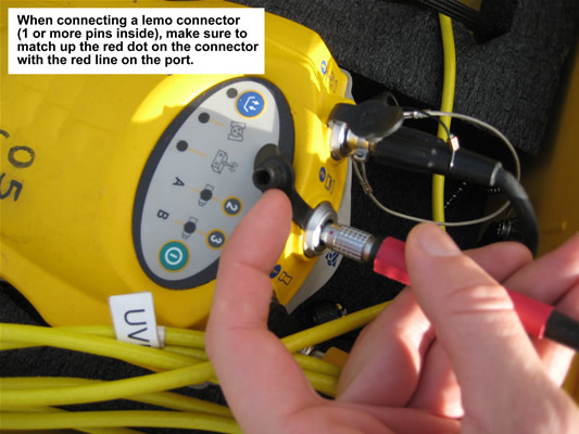
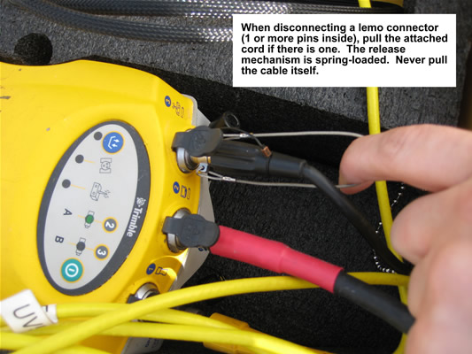
Connecting and disconnecting lemo connectors to and from the GPS receiver.
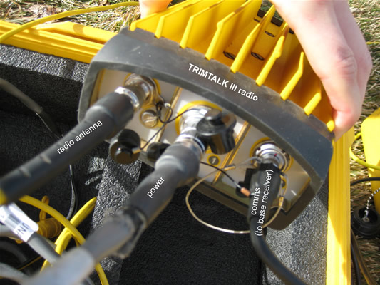
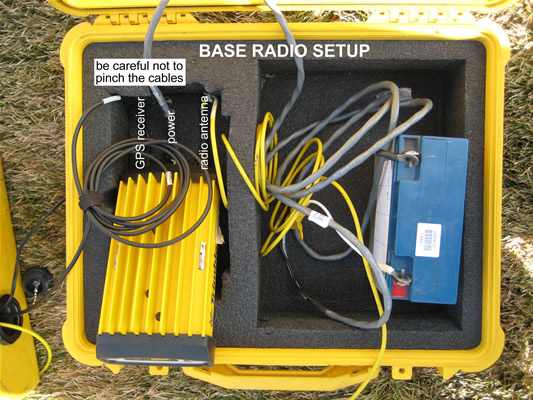
Base radio setup.
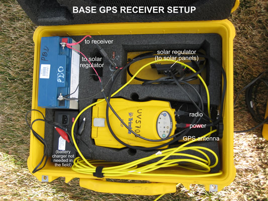
Base receiver and overall base station setup.
As with the base station, rover antenna setup may vary depending on the project goals. The suggested setup includes an antenna mounted on either a backpack mount (lower precision) or a range pole (higher precision).
Connect the GPS antenna to the antenna mount.
Connect the 90 degree end of the antenna cable to the antenna; uncoil just enough cable to reach from the antenna to the survey backpack with a small amount of slack. Place the rest of the cable, still coiled, inside the backpack. This will help to keep the cable tidy and unkinked. [If using a Trimble survey backpack, uncoil the appropriate amount of cable first and place the still-coiled cable in the backpack; pass the uncoiled end of the cable through one of the openings in the back of the backpack and connect the end to the antenna.]
If using internal batteries, put the internal batteries in the receiver and place the receiver in the backpack with the ports facing upwards. If using an external battery, put the battery in the survey backpack with the terminals protected and place the reciever on top of or beside it with the ports facing upwards. Connect the battery to the receiver using the battery cable and port 2 or 3 of the receiver.
Connect the straight end of the GPS antenna cable to the GPS antenna port on the receiver.
If using a receiver with an internal radio, connect the radio antenna to the radio antenna port on the receiver. If using an external radio, connect the radio antenna to the survey backpack and to the rover radio; connect the rover radio to port 3 of the GPS receiver.
Connect the survey controller cable to port 1 on the receiver using the survey controller cable. If using a Trimble survey backpack, pass the cable through one of the openings in the back of the backpack.
Turn on the survey controller and the receiver if they are not on already. As with the base, you should see receiver, antenna, and satellite icons on the controller’s screen. You should also see a radio icon. If you do not see the radio icon, there is probably a problem with your radio link. Proceed to the next step anyway, and then troubleshoot as needed.
Connect to the rover radio:
From the main menu, select Configuration-->Survey Styles-->RTK-->Rover Radio-->Connect
Confirm that Base Radio Mode matches the Wireless Mode on the TRIMMARK 3, e.g. TRIMMARK 3 at 19200 bps. Confirm that Base Radio Frequency matches the Channel Frequency on the TRIMMARK 3, e.g. 461.1000 MHz. Return to the main menu.
Select Survey in the lower left. Select your chosen survey style (e.g. RTK). Select "Start survey".
Highlight the appropriate base station (usually 29) and hit "Accept". If you do not get a base station option and the following screen does not appear, proceed to Troubleshooting, below.
A "Starting survey" screen with a progress bar should appear. A radio icon should appear in the upper right with the receiver and satellite icons. At the bottom of the screen, the controller will display survey messages and measurement precision. Possible messages are e.g. "No radio link," "Searching for satellites," "Poor PDOP," and "Initializing, please wait". Precision is displayed as "RTK: [Float/Fixed] H: xx V:xx" where the H and V values represent repeatability in the horizontal and vertical, respectively. ’Float’ indicates the position is low precision; the base and rover receivers do not have enough satellites in common for long enough to confidently determine relative positions. ’Float’ values are generally on the order of meters. ’Fixed’ indicates enough data has been tracked to calculate high-confidence positions; ’Fixed’ values are generally on the order of centimeters. You must have a ’Fixed’ solution before proceeding. The message "Initializing, please wait" simply means the system is acquiring a ’Fixed’ solution. If there is a problem with your radio link (the radio link icon has disappeared or the "No radio link" message is displayed), see Troubleshooting, below. If there is a positioning problem ("Searching for satellites," "Poor PDOP," or a continued ’Float’ solution) move into a clearer area to increase the rover antenna’s sky view. As stated before, you must track at least 5 satellites in common with the base receiver.
To measure topo points:
Select Survey from the lower left of the main menu. Select "Measure points".
Name the point and enter the antenna information. Select "Measure". DO NOT MOVE UNTIL POINT IS STORED. If you have set ’Auto store point’ to ’Yes’ in the survey configuration, your point survey will automatically stop after the required time or when the required precision has been met. If you have set it to ’No,’ you will have to end the point survey by selecting "End".
Continue to measure points as needed.
Hit the Menu or Esc key/option to return to the main menu.
To measure points continuously (mapping):
Select Survey from the lower left of the main menu. Select "Continuous topo".
Select survey method (fixed time and/or distance). This will determine how frequently data are collected. Complete antenna information. Select time and/or distance interval. Points will be collected automatically based on this setting. Give a start point name; we highly recommend your point name ends in a number, as this last character will automatically be incremented in each point name.
Select "Measure" when ready.
Select "End" when done. Start and end point collection as much as needed.
Hit the Menu or Esc key/option to return to the main menu.
To navigate to known points (stakeout):
Note: Not all Stakeout features will be available if you have not selected a coordinate projection in your survey style.
Select Survey from the lower left of the main menu. Select "Stakeout".
Select "Stakeout" -> "Points". If your point is not listed, select "Add" -> "Select from list". Select point(s), hit "Add". (You must select, not just highlight, a point.) Note that any point collected in your survey should be in your point list. Highlight the desired point from the new list; select "Stakeout". To add previously determined points to your survey, see Specific survey scenarios, Scenario 1: Use coordinates from a past survey, below.
Navigate to the point using the display. In ’coarse mode’, walk forwards at a normal pace being careful not to rotate the range-pole. The arrow on the screen is only meaningful if you are moving, as the GPS antenna calculates direction based on how the antenna’s position is changing. Begin moving and then follow the arrow. Once you are close to your point, the screen will switch to ’fine mode’ and a bulls eye will appear. At this point, do not turn; navigate by moving only forward and backward or side to side.
If you want to record your location, select "Measure". Enter the point information and select "Measure" when done. When the solution is obtained, select "Store".
Hit the Menu or Esc key/option to return to the main menu.
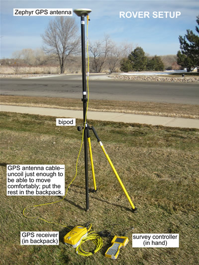
Rover setup.
When you are done with your survey, press the Menu key to return to the main menu and select Survey from the lower left.
Select "End Survey". You can start and end a survey in the same job as many times as you like. When asked "Power down receiver?" select "Yes".
The message "Disconnect the cable from the controller" will appear. Disconnect the cable from the receiver and hit "OK".
Power down the survey controller by pressing and holding the green power key for 2 seconds. Do NOT continue to press the power button after the survey contoller begins powering down - this will force a hard reset.
If you have not already powered down the rover receiver, do so now by pressing and holding the green power button for 2 seconds. Do not continue to press the power button after the receiver has powered down.
Disassemble the rover equipment in any order. To disconnect cables from ports 1-3 on the receiver, pull the connectors straight out using the small metal cable attached to the connector. If there is no attached cable, grasp the upper part (closest to the cable, not the receiver) and pull. Do not force the connectors and NEVER TWIST the connectors, as the pins inside may break.
Return equipment to the original containers.
There is no need to reconnect the survey controller to the base station. Simply power down the receiver by removing the power cord if using external power, or by pressing and holding the power button for 2 seconds if using internal batteries (do not continue to press the power button after the receiver has powered down).
Remeasure the antenna height; check that the antenna is level and oriented to north. Note any problems with the antenna set-up.
Disassemble the base equipment in any order. To disconnect cables from ports 1-3 on the receiver, pull the connectors straight out using the small metal cable attached to the connector. If there is no attached cable, grasp the upper part (closest to the cable, not the receiver) and pull. Do not force the connectors and NEVER TWIST the connectors, as the pins inside may break.
Coil the cables carefully without kinking or twisting the cables. DO NOT coil the antenna cable around your arm, as this twists the cable.
Return equipment to the original containers.
Getting set up for RTK surveys can be quite finicky. If you are having trouble getting your base and rover to communicate via radio link, address the following:
Are both the base and the rover set to CMR+ (in "Broadcast format" in the survey style on the controller)?
Is the correct antenna type in the survey style for both the base and the rover?
Is the correct radio type in the survey style for both the base and the rover?
Is the power setting for the base radio appropriate for the distance between the base and rover?
Do the base radio frequency and wireless mode settings match on the base and the rover?
Is the coordinate system appropriate for the region?
Power the receivers and survey controller off and then back on, and restart the base with the survey controller. Sometimes a power cycle is all that is needed.
There are two ways to add predetermined coordinates to a current job: Enter the coordinates by hand or upload the coordinates from Trimble Geomatics Office (TGO).
To enter coordinates by hand into the survey controller:
Make sure you are in the right job. The job name appears across the top of the screen.
From the main menu, select "Key in" -> "Points".
Enter the point name and coordinate information. MAKE SURE YOU ARE IN THE CORRECT COORDINATE SYSTEM. If not, go to Options and change the coordinate view. The job will only support one coordinate system set; if your coordinates are given in a different coordinate system than you will be surveying in, you must convert the coordinates into the current system before entering them into the controller. You can use online tools or TGO for coordinate system conversions.
To upload coordinates using TGO:
In TGO, open the project that you want to use. If your coordinates are in a spreadsheet and not a project, create a new job (see the Data Processing section), select Import -> Other Survey Files and select the appropriate data format. Choose the file, click Open. The points should appear on the screen if imported correctly. Select View-->Point Names to check.
Connect the survey controller to the computer if it is not connected already (see the Data Processing section, below).
Select Export from the left-hand menu. Select Survey Device. If using the UNAVCO RTK system, select Survey Controller on ActiveSync. Hit Open.
You should see the controller’s existing jobs listed, with the TGO project as the File name listed below. Click Save. The project should send.
Check that the points were transferred to the survey controller from the survey controller main menu by selecting Files -> Open job -> select the newly imported job and hit Select. Again from the main menu, select Files -> Review current job. The points should be listed.
If you want to add the newly imported points to an existing job rather than starting a new one, select Files from the main menu. Select Copy between jobs. Enter the job names and under Copy select Points. Hit Accept. When prompted, select the point set you would like copied.
Load the previous survey’s grid coordinates onto the survey controller (see Scenario 1).
Program the base with the survey controller to accept its position as "Here".
Choose a previously surveyed point to serve as your reference point in the survey.
Survey the reference point with the rover in WGS84 coordinates; name the site something different from what it was named before.
Perform a calibration: After you have started your survey, select Survey in the low left of the main menu. Select ’Site calibration’. Select the GPS point (the newly surveyed point in WGS84). Select the grid point (previously survey version of the same point, in grid coordinates). Hit "OK".
The two points (new WGS84, old grid) now appear as one. You can now survey the other points relative to your reference point. By leaving the survey in grid mode, you can ulitize the map feature on the survey controller.
There are several options for downloading data from the GPS receiver and the survey controller.
You will need the Trimble Data Transfer Utility. If you do not already have it loaded onto your computer, you can dowload it for free from the Trimble website (http://www.trimble.com/datatransfer.shtml) or the UNAVCO Knowledgebase (/questions/603/).
![]()
Screen shot of the Trimble Data Transfer Utility.
Connect the receiver or survey controller to a PC using the communications cable (4700, 5700, R7, TSC1) or a USB cable and dongle (TSCe). The communications cable is a serial cable; if using a laptop, you may need to use a serial-to-USB adapter. Power up the computer and the receiver or survey controller. If using a TSCe, the following message should appear: "Connect to desktop?" Select "Yes". A Microsoft ActiveSync window should appear on your computer screen, readying "Connected". If you do not have Microsoft ActiveSync, download it for free from Microsoft (http://www.microsoft.com/windowsmobile/en-us/help/synchronize/device-synch.mspx).
Open Trimble Data Transfer Utility.
If you do not connect automatically ("Connected to ..". message in the upper right), select the device from which you’d like to transfer data. If your device is not listed in the drop-down menu:
Click the "Devices" button.
Select "New" (lower left).
Select device from list, click "Okay".
Select the computer’s comm port that you are using, click "Next".
Enter a name for your device.
Set the serial port properties. Defaults should be fine; make sure "Data bits" = 8 and "Parity" = None. Click "Finish".
Click "Close" in the "Devices" window.
Your new device should now be added to the drop-down list.
Click the button with the green check mark.
Click "Add". In the "Open" window, browse for the folder you would like your data transfered into under "Destination".
Select the file(s) you would like transfered. Note that the file(s) will be named for the job(s) you created. Click "Open".
The selected file(s) should appear in the main Data Transfer Utility window. Click "Transfer All".
Close the Data Transfer Utility program and disconnet the survey controller.
The program will automatically convert .t01 and .t00 files to .dat files; both file types will be transfered to your computer, along with metadata (the ’job’ files). If you did not collect any raw data (rtk + infill), you will not have any .t01, .t00, or .dat files.
This option is the easiest, but is not recommended for transfering any data that has been collected with the survey controller because of the potential for losing metadata (see Option 1). You may want to use this method for downloading data from your base receiver, if you stored data.
Insert the compact flash or PCMCIA card (TSC1 only) into the appropriate card reader connected to a computer.
Select the files from the card that you wish to transfer; copy them to a directory on your computer.
On your computer, right-click on the file(s). Select "Convert to .DAT". A .dat file for each file selected will be created in the same directory. You must have the Trimble Data Transfer Utility on your computer to have access to this option.
Back up your data.
By pulling your data into Trimble Geomatics Office (TGO), you can view your survey and adjust the coordinate system as needed, and output points into a spreadsheet format. If you collected data for post-processing, see How to process fast-static and post-processing kinematic surveys using TGO (/questions/613/).
Screen shot of Trimble Geomatics Office software.
Open TGO. Select "New Project".
Give the project a name. For template, select Metric. Click Okay.
Change Project Properties as needed. In particular, click on the Coordinate System tab and change to the coordinate system used in your survey. Note that other properties can be easily adjusted after data import by selecting Projects from the left-hand menu/tab and then selecting Project Properties.
The map should be blank. Select Import from the left-hand menu/tabs.
Select Survey Controller DC File from the left-hand Import menu.
Browse for and select your job (.dc) file and hit Open.
Error messages are not uncommon and can often be ignored. Still, it’s a good idea to review the import report to see if there is an understandable error.
Your points should now be visible on the map. Blue lines indicate baselines, or distance and direction from the base station to the rover(s). Light blue baselines are ’Continuous’ observations; dark blue baselines are ’Topo points’. Double-click on a point to see its coordinates or on a baseline to see error estimates and other information.
A flag and the message "Low quality starting point" will appear over the base if you did not give the base its coordinates in the field. To change this base to known coordinates (and allow the other points to adjust accordingly), double-click on the base point. In the resulting window, click on the ’beach ball’ in the upper right and select the appropriate coordinate system. Enter the desired coordinates and change the confidence levels in the drop-down menus on the right to Control Quality. Select the field coordinate (indicated with a ’beach ball’) from the list on the left. Delete this coordinate by clicking the red ’x’ in the upper right. This coordinate will still exist in your origninal job file. Close the Properties box. Select "Survey" from the upper menu and then "Recompute". The entire survey should now be adjusted for the correct base coordinates.
Export your data in a comma delimited format appropriate for spreadsheets e.g. Excel. Select the Export menu/tab from the left-hand menu and then Pt,N,E,E,Code. Select Custom from the top tabs. Select the appropriate information for export (or select New format... and create your own combination), click OK.
Close TGO when done. Your project is automatically saved.
bab2010
Article ID: 617
Created: May 16, 2012
Last Updated: May 16, 2012
Author: Beth Bartel
Online URL: https://kb.unavco.org/article/trimble-4700-5700-r7-how-to-execute-a-real-time-kinematic-rtk-survey-from-start-to-finish-617.html