Configuration 1 - Standard atmospheric (and geodetic) site
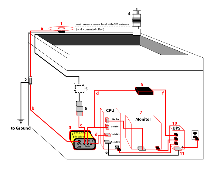
All components are typically in the same building, but the GPS antenna may be mounted on a seperate monument to improve stability and/or sky visibility. [Right-click on the diagram below and select "View Image" for a larger version.]

[See components key under Configuration 3, below.]
Configuration 2 - Atmospheric AND geodetic site
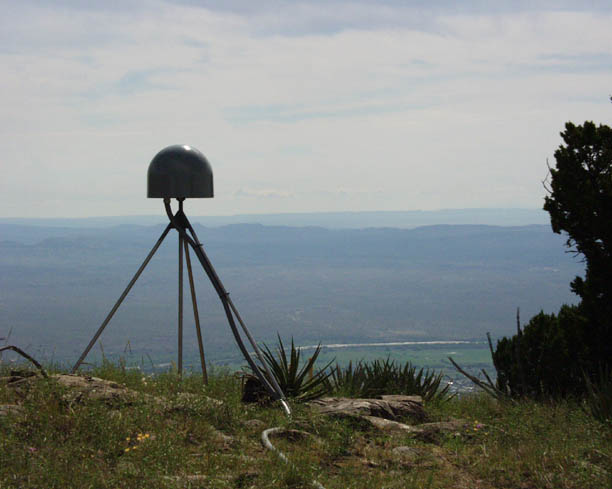
Same as Configuration 1, except using an IGS chokering antenna, SCIGN antenna mount, and a SCIGN Tall radome. These are supported on a LIMITED basis. Contact Bjorn Johns (bjorn![]() unavco.org) at UNAVCO for more information.
unavco.org) at UNAVCO for more information.

Configuration 3 - Standard atmospheric or atmospheric/geodetic site with a radio modem link
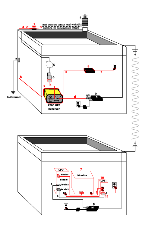
Like Configuration 1, except with a radio modem link for the serial connection between the GPS receiver and the computer. In this configuration, only one serial link is used.

Configuration 3 Components:
1. Trimble Microcentered geodetic GPS antenna
2. Grounded lightning protector
3. Trimble 4700 GPS receiver
4. Meteorological package sensor
5. Meteorological package body (Vaisala only)
6. Serial surge protector
7. System computer
8. Trimble power supply p/n 30413
9. Wireless radio
10. Backup power supply
11. Gen power connector
Cables:
a. GPS antenna cable - N male to N male, RG-214
b. GPS antenna cable - N male to 1-shell Lemo Coaxial P male, RG-214
c. GPS to meteorological package cable - 0-shell Lemo male to DB9 male
d. Serial/power cable p/n 32345 - 7 p Lemo to DB9
e. Serial cable - DB9 male to DB9 female
f. Power cable
g. DB9 null modem adapter
h. DB9 male-male adapter
Configuration 4 - Atmospheric/geodetic site with a radio modem link
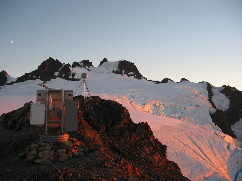
Like Configuration 2, except with a radio modem link for the serial connection between the GPS receiver and the computer. In this configuration, only one serial link is used.
