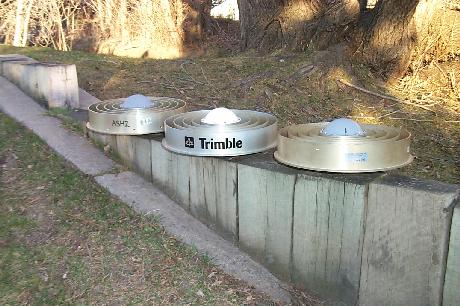
Pictured above from left to right are antennas from Ashtech, Trimble, and Allen Osborne & Associates. With an increase in the number of companies offering a choke ring antenna, it is important that any differences is the dimensions from one antenna to another are noted. UNAVCO measured the dimensions of the Trimble Navigation, Ashtech, Allen Osborne & Associates, and Leika choke ring antennae.

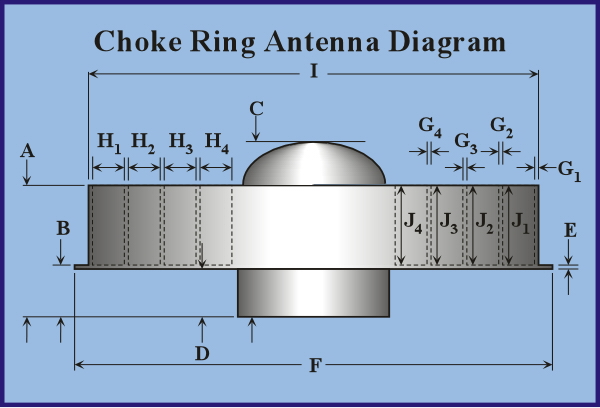
This is a diagram of a generic choke ring antenna, defining the various standard dimensions (which are noted in the table below). Also noted in the table is the Difference in mm from the IGS reported values for those dimensions.
For more information on GPS Antenna Testing and Calibration, please see the The NGS/NOAA Antenna Calibration Page. Inside the table below, the NGS/NOAA test results for each specific antenna model are linked directly to the model number when available. Select the link to see the results.
Also of interest is the SCIGN (Southern California Integrated GPS Network) Website.
| Dimensions of Manufactured Choke Ring Antennae | ||||||||||||||||||
|---|---|---|---|---|---|---|---|---|---|---|---|---|---|---|---|---|---|---|
|
|
AOA | Trimble | Leica | Ashtech "D" | Ashtech "E" | Ashtech "B" | ||||||||||||
| Model | 7490582-2 | 29659-00 | 10839 | 700936 | 700936-02 | 701945-02 | ||||||||||||
| DMC Element | C 146-6-1 S/N 2243 | C 146-6-1 S/N 1993 | C 146-10-1 S/N 2839 | C 146-10-1 S/N 2821-10 | C 146-10-1 S/N 1306 | unk | ||||||||||||
| SCIGN | NO | NO | YES | YES | YES | YES | ||||||||||||
| Units | Inches | mm | Diff IGS | Inches | mm | Diff IGS | Inches | mm | Diff IGS | Inches | mm | Diff IGS | Inches | mm | Diff IGS | Inches | mm | Diff IGS |
| "A" | 3.988 | 101.3 | 0.70 | 4 | 101.6 | 0.40 | 3.984 | 101.2 | 0.81 | 3.97 | 100.8 | 1.16 | 3.992 | 101.4 | 0.60 | 3.972 | 100.9 | 1.11 |
| "B" | 1.584 | 40.2 | -2.23 | 1.497 | 38.0 | -0.02 | 1.487 | 37.8 | 0.23 | 1.489 | 37.8 | 0.18 | 1.51 | 38.4 | -0.35 | 1.594 | 40.5 | -2.49 |
| "C" | 5.482 | 139.2 | 5.508 | 139.9 | 5.475 | 139.1 | 5.453 | 138.5 | 5.475 | 139.1 | ||||||||
| "D" | 1.37 | 34.8 | 0.20 | 1.375 | 34.9 | 0.08 | 1.359 | 34.5 | 0.48 | 1.365 | 34.7 | 0.33 | 1.38 | 35.1 | -0.05 | 1.37 | 34.8 | 0.20 |
| "E" | 0.12 | 3.0 | -0.05 | 0.12 | 3.0 | -0.05 | 0.125 | 3.2 | -0.18 | 0.119 | 3.0 | -0.02 | 0.14 | 3.6 | -0.56 | 0.122 | 3.1 | -0.10 |
| "F" | 14.9375 | 379.4 | 1.59 | 15.01 | 381.3 | -0.25 | 14.9375 | 379.4 | 1.59 | 14.9375 | 379.4 | 1.59 | 14.9375 | 379.4 | 1.59 | |||
| "G1" | 0.139 | 3.5 | 0.125 | 3.2 | 0.135 | 3.4 | 0.13 | 3.3 | 0.145 | 3.7 | 0.129 | 3.3 | ||||||
| "G2" | 0.139 | 3.5 | 0.125 | 3.2 | 0.132 | 3.4 | 0.13 | 3.3 | 0.145 | 3.7 | 0.129 | 3.3 | ||||||
| "G3" | 0.137 | 3.5 | 0.125 | 3.2 | 0.132 | 3.4 | 0.13 | 3.3 | 0.143 | 3.6 | 0.129 | 3.3 | ||||||
| "G4" | 0.137 | 3.5 | 0.125 | 3.2 | 0.132 | 3.4 | 0.13 | 3.3 | 0.143 | 3.6 | 0.129 | 3.3 | ||||||
| "H1" | 0.999 | 25.4 | 0.998 | 25.3 | 0.99 | 25.1 | 0.994 | 25.2 | 0.99 | 25.1 | 1.0 | 25.4 | ||||||
| "H2" | 0.981 | 24.9 | 1.002 | 25.5 | 1 | 25.4 | 0.998 | 25.3 | 0.988 | 25.1 | 1.0 | 25.4 | ||||||
| "H3" | 0.99 | 25.1 | 1 | 25.4 | 1 | 25.4 | 0.998 | 25.3 | 0.99 | 25.1 | 1.0 | 25.4 | ||||||
| "H4" | 0.994 | 25.2 | 1 | 25.4 | 0.99 | 25.1 | 0.998 | 25.3 | 0.99 | 25.1 | 1.0 | 25.4 | ||||||
| "I" | 14.1675 | 359.9 | 14.173 | 360.0 | 14.134 | 359.0 | ||||||||||||
| "J1" | 2.505 | 63.6 | 2.500 | 63.5 | 2.000 | 50.8 | 2.475 | 62.9 | 2.490 | 63.2 | 2.475 | 62.9 | ||||||
| "J2" | 2.505 | 63.6 | 2.500 | 63.5 | 2.000 | 50.8 | 2.478 | 62.9 | 2.491 | 63.2 | 2.477 | 62.9 | ||||||
| "J3" | 2.505 | 63.6 | 2.500 | 63.5 | 2.000 | 50.8 | 2.478 | 62.9 | 2.491 | 63.3 | 2.476 | 62.9 | ||||||
| "J4" | 2.501 | 63.5 | 2.500 | 63.5 | 2.000 | 50.8 | 2.478 | 62.9 | 2.491 | 63.3 | 2.479 | 63.0 | ||||||
Article ID: 311
Created: March 24, 2010
Last Updated: March 24, 2010
Author: Victoria Andreatta
Online URL: https://kb.unavco.org/article/choke-ring-antenna-calibrations-311.html