How To: build a simple digital temperature sensor with RS232 serial interface
Temperature Sensor With RS232 Serial Interface
The purpose of this article is to present a method for creating a low-cost temperature sensor that can communicate over an RS232 serial connection with a Trimble GPS receiver. The temperature data can then be logged to the receiver’s internal memory or streamed on a TCP port via the BINEX or RT27 formats. This sensor is intended to be used with a Trimble NetRS/NetR5/NetR8/NetR9 receiver by enabling the Tilt/Met logging feature on the receiver. It may be possible to use this device with other receivers if they support met sensors.
This article will document the following: the materials needed to build the project; how to program the sensor to communicate with the receiver; and how to set up the receiver to communicate with the sensor. The main application for this sensor is to log temperature data at a GPS site. Previous knowledge of basic soldering/electronics skills are required.
This tutorial does not include instruction on how to build an enclosure for this device. The size of the sensor could be reduced by choosing smaller components (e.g. Arduino Nano, Arduino Mini).
Components
- 1 Arduino Uno (available from multiple vendors e.g. sparkfun.com)
- 1 one wire digital temperature sensor - DS18B20 (http://www.adafruit.com/products/381)
- 1 1/4 W 4.7kOhm resistor (usually comes with the temp sensor)
- 1 RS232 shifter board (http://www.sparkfun.com/products/449)
- wire (multiple colors are helpful)
Tools
- leaded or lead free solder
- soldering iron
- Phillips head screw driver
- wire cutters/strippers
Schematic
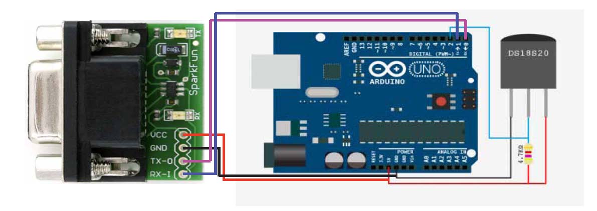
The wiring diagram for the Arduino Uno, DS18S20 1-wire temperature sensor and the RS232 shifter board is shown below. The size of each component is not to scale. In this configuration, the DS18S20 temperature sensor requires a pull-up resistor (1/4W 4.7kOhm) between the 5V (red) and Data (blue) wires.
Programing the Sensor
- Download the Arduino sketch located here. The zipped folder contains the program that will allow the Arduino to communicate with the receiver and the temperature sensor. Unzip the folder after downloading.
- If it’s not already installed, download and install the latest Arduino Software for your computer (http://www.arduino.cc/en/Main/Software).
- If you use the Arduino’s USB port for programming, disconnect the RS232 shifter from the Arduino before programing. The RS232 board can interfere with the USB connection. Alternatively, you can use the RS232 connection to program the Arduino. I recommend using the USB port.
- Connect the USB port from the Arduino to the USB port on your computer. The USB connection will provide power and a data connection to the Arduino.
- Open the Arduino Software on your computer.
- Select the serial port for your device (Tools -> Serial Port -> Your Device’s port)
- Select the Arduino board type (Tools -> Board -> Arduino Uno)
- Open the Arduino sketch (File -> Open...)
- Choose the file called "serial_onewire_temp" from the folder that you downloaded in step 1.
- In the upper left-hand corner of the serial_onewire_temp window, click on the right hand arrow. Doing so will upload the script to the the connected Arduino.
- Your Arduino should now be programmed correctly to communicate with both the receiver and the temperature sensor.
Programing the Receiver (for Trimble NetR9)
- Go to the receiver’s web interface
- click on I/O Configuration
- Select the serial port that you would like to connect the sensor to
- Select Met-Tilt from the drop down menu
- Select a baud rate of 19,200
- Parity: N
- Flow: Disabled
- in the "Command" column, type a capital "R" in the first row
- select the desired logging rate (1sec - 4hrs) in the Schedule column in the same row
Connect the device to your receiver using a serial cable.
Once both the Arduino and the Receiver are configured correctly, connect the two devices with a serial cable. The Arduino will need to be powered by a 7-12V DC power source using a center positive barrel plug. The Arduino will automatically run the uploaded sketch when powered up. The temperature sensor design shown in this report will consume ~0.4W. The Met data from the sensor will be included in logged session files (T00, T01, T02), or if selected, in RT17/RT27/BINEX streaming formats. The DS18S20 temperature sensor has an operating temperature range of -55°C to +125°C and is accurate to ±0.5°C over the range of -10°C to +85°C. In this example the DS18S20 has a resolution of 9-bits.
)