)
Power - Effects of Lightning Electromagnetic Pulse (LEMP) Protection on GPS Signals (1997)
NOTE: This is a dated document. Please refer to this document for historical puposes only. The equipment documented here has since been updated and or replaced. New product evaluations will appear here as they are available.
Curt Conquest, Bruce Stephens, and Teresa Van Hove - 3/19/97
Introduction
Many continuously operating GPS networks are located in areas with severe storms and high lightning activity. To avoid damaging the equipment and interrupting the data flow, it is advisable to use surge and lighting protection to dissipate the energy from lightning strikes or surges in the power grid. The UNAVCO Boulder facility performed preliminary tests on two LEMP devices for use between the GPS antenna and receiver and the radio modem antenna and transceiver. Tests were conducted to determine the affect of the LEMP on the GPS signal. The Alpha Delta R-T/N and the Huber Suhner 3402.17.K with a 73Z-0-0-48 gas capsule were tested. The Alpha Delta was chosen for testing as it is being used at the US Coast Guard’s CORS network. The Huber Suhner, used on other radar installations such as the Buckley Air National Guard base, was recommended by Exelcis, a local representative of several RF and Microwave products.
These LEMP devices are used in series with the antenna cable for the GPS and data communications equipment. They were tested on the bench for group delay, insertion loss, VSWR, and impedance matching (reflected signals) as a function of frequency. The graphs and table below show the results from these tests using a HP 8753C Network Analyzer. They were also tested in a Zero Baseline (ZBL) survey, using two Trimble SSI receivers.
Description of Bench Test Set Up
The LEMP’s were tested using an HP 8753C Network Analyzer, as illustrated below. There is one differences between the Alpha Delta and the Huber Suhner protectors. The Alpha Delta device uses an external drain (grounding) wire. In the bench tests, the drain wire was bonded to the shield of the cables from the HP 8753C. The Huber Suhner uses an internal drain.
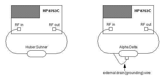
Figure 1: Setup of LEMP’s with HP8753C Network Analyzer
Group Delay
Figures 2 and 3 show the group delay as a function of frequency for the Alpha Delta and Huber Suhner respectively. The L1 frequency is shown by the small arrowhead 2 and the L2 frequency is shown by the small arrowhead 1. The x-axis is frequency with a center frequency of 1.5 GHz and a span of 1.0GHz. The y-axis is delay in time. The reference line for the delay axis for the Alpha Delta is 200 pico seconds with 200 pico seconds/division as a scale and the delay axis for the Huber Suhner is 150 pico seconds with 50 pico seconds/division as a scale. The Huber Suhner had a group delay of 126.65 pico seconds at L1 and 97.656 pico seconds at L2, as a function of frequency. The Alpha Delta had a group delay of 180.05 pico seconds at L1 and 406.65 pico seconds at L2. The large notch on the Alpha Delta plot is a region that the L1 center frequency can change the delay value (a function of Doppler frequency shift) depending if the satellites are rising, overhead or setting.

Figure 2: Graph of group delay for Alpha Delta LEMP

Figure 3: Graph of group delay for Huber Suhner LEMP
Insertion Loss
Figures 4 and 5 show the insertion loss as a function of frequency for the Alpha Delta and Huber Suhner respectively. The L1 frequency is shown by the small arrowhead 2 and the L2 frequency is shown by the small arrowhead 1. The x-axis for both is the frequency with a center frequency of 1.5 GHz and a span of 1.0 GHz.The y-axis is RF loss (dB) and the reference line for both graphs is 0 dB with 10 dB/division as a scale. The Huber Suhner has an insertion loss of 0.032 dB at 1575 MHz (L1) and 0.0012 dB at 1200MHz (L2). The Alpha Delta has an insertion loss of 2.11 dB at L1 and 0.168 dB at L2. A higher insertion loss will decrease the signal-to-noise ratio which could also limit the length of the antenna cable (e.g. RG214 has approximately a loss of 10dB/100ft). A standard value used by most GPS manufactures is 12 dB maximum loss between the GPS receiver and its antenna.

Figure 4: Graph of insertion loss for the Alpha Delta LEMP

Figure 5: Graph of insertion loss for the Huber Suhner LEMP
Reflected Signal
Figures 6 and 7 are Smith Charts that show impedance matching as a function of frequency. The L1 frequency is shown by the small arrowhead 2 and the L2 frequency is shown by the small arrowhead 1. The charts show the impedance at each frequency measured with the center line at 50 Ohms impedance. Figure 6, the Alpha Delta, shows that L1 and L2 vary in capacitance, inductance, and impedance with frequency. Figure 7, the Huber Suhner, stays very close to 50 Ohms with very little capacitive or inductive reactance. The Alpha Delta has a reflected signal of, -9.46 dB at L1 and -24.23dB at L2. The Huber Suhner has a reflected signal of -36.94 dB at L1 and -33.45 dB at L2. The Alpha Delta is passing less signal to the receiver. The results for the Alpha Delta were significantly affected by moving the grounding wire or even touching it. The results shown here are for the setup drawn in Figure 1. The Huber Suhner was not affected by any outside influence. These affects were not seen in the ZBL results. Improper impedance matching is another cause for the lower signal passed to the GPS receiver.

Figure 6: Smith chart of Alpha Delta LEMP

Figure 7: Smith Chart of Huber Suhner LEMP.
Description of Zero Base Line (ZBL) Test Set Up
The lightning protectors affect on GPS data was assessed by running a zero-baseline survey as shown in the following figure. A choke ring antenna was connected to a splitter. One Trimble 4000 SSI receiver powered the antenna and received signals (Rx 1). A second Trimble 4000 SSI receiver was connected to the splitter with a D.C. block so that it only received signals (Rx 2). The powering receiver had the LEMP inserted for two days. Then the LEMP was removed and the receivers were run in this zero baseline mode for two more days The receivers collected data at a 30 sec. sample rate.
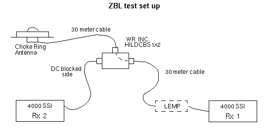
Figure 8: Set up for Zero Baseline test.
Data Testing
Signal to noise ratios (SNR’s) were compared for the two receivers with the LEMP installed on Rx 1 and Rx 2 connected directly to the splitter. SNR differences were calculated by (SNR of Rx 1 - SNR of Rx 2). The percent of SNR differences were calculated by (SNR of Rx 1 - SNR of Rx 2 / SNR of Rx 2). Note that there is no direct correlation between the percent of change in SNR’s and the percent of change in the RF signal. The Alpha Delta LEMP reduced the L1 and L2 SNR about 1%. The Huber Suhner LEMP reduced the L1 SNR about 3% and the L2 SNR about 1% (see Tables 1 & 2). The L2 SNR is about 10% lower than the L1 SNR ratio for standard data collection with A/S on.
Table 1: Signal to Noise for Alpha Delta’s LEMP| elev | L1 SNR diff. | % L1 SNR diff. | L1 SNR diff. with surge protector | % L1 SNR diff. with surge protector | L2 SNR diff. | % L2 SNR diff. | L2 SNR diff. with surge protector | % L2 SNR diff. with surge protector |
|---|---|---|---|---|---|---|---|---|
| 90 | -1.936 | -6.382 | -2.198 | -7.377 | -0.973 | -3.220 | -0.988 | -3.294 |
| 85 | -1.616 | -5.114 | -1.463 | -4.609 | -1.023 | -3.247 | -1.026 | -3.250 |
| 80 | -1.201 | -3.716 | -1.213 | -3.744 | -1.074 | -3.430 | -1.037 | -3.293 |
| 75 | -1.239 | -3.849 | -1.487 | -4.643 | -0.964 | -3.157 | -0.997 | -3.282 |
| 70 | -1.338 | -4.186 | -1.680 | -5.313 | -0.859 | -2.898 | -1.011 | -3.443 |
| 65 | -1.772 | -5.769 | -1.944 | -6.312 | -0.872 | -3.093 | -0.932 | -3.304 |
| 60 | -1.824 | -6.219 | -2.059 | -7.037 | -0.815 | -3.084 | -0.850 | -3.220 |
| 55 | -1.797 | -6.564 | -2.008 | -7.344 | -0.799 | -3.256 | -0.798 | -3.255 |
| 50 | -1.588 | -6.477 | -1.828 | -7.476 | -0.676 | -3.106 | -0.683 | -3.144 |
| 45 | -1.384 | -6.395 | -1.636 | -7.607 | -0.571 | -2.960 | -0.643 | -3.345 |
| 40 | -1.201 | -6.497 | -1.386 | -7.451 | -0.515 | -3.098 | -0.551 | -3.292 |
| 35 | -1.008 | -6.417 | -1.176 | -7.533 | -0.423 | -2.984 | -0.450 | -3.196 |
| 30 | -0.836 | -6.571 | -0.969 | -7.610 | -0.354 | -3.028 | -0.386 | -3.299 |
| 25 | -0.687 | -6.550 | -0.797 | -7.662 | -0.275 | -2.857 | -0.295 | -3.088 |
| 20 | -0.564 | -6.671 | -0.650 | -7.687 | -0.231 | -2.925 | -0.254 | -3.219 |
| 15 | -0.497 | -6.853 | -0.558 | -7.715 | -0.215 | -3.240 | -0.195 | -2.942 |
| 10 | -0.361 | -6.773 | -0.410 | -7.694 | -0.098 | -1.884 | -0.172 | -3.312 |
| 5 | -0.152 | -3.925 | -0.212 | -5.481 | -0.011 | -0.233 | -0.178 | -3.852 |
Table 2: Signal to Noise for Huber Suhner’s LEMP
| elev | L1 SNR diff. | % L1 SNR diff. | L1 SNR diff. with surge protector | % L1 SNR diff. with surge protector | L2 SNR diff. | % L2 SNR diff. | L2 SNR diff. with surge protector | % L2 SNR diff. with surge protector |
|---|---|---|---|---|---|---|---|---|
| 90 | 1.205 | 3.790 | -0.066 | -0.201 | 0.302 | 0.973 | -0.169 | -0.532 |
| 85 | 0.395 | 1.183 | -0.001 | -0.003 | 0.308 | 0.927 | -0.138 | -0.416 |
| 80 | 0.396 | 1.182 | 0.010 | 0.030 | 0.217 | 0.678 | -0.167 | -0.523 |
| 75 | 0.402 | 1.201 | 0.000 | 0.000 | 0.246 | 0.783 | -0.171 | -0.545 |
| 70 | 0.565 | 1.706 | -0.001 | -0.003 | 0.289 | 0.951 | -0.154 | -0.506 |
| 65 | 0.763 | 2.345 | -0.039 | -0.118 | 0.233 | 0.795 | -0.184 | -0.628 |
| 60 | 0.996 | 3.204 | -0.101 | -0.317 | 0.210 | 0.765 | -0.189 | -0.688 |
| 55 | 0.842 | 2.967 | -0.159 | -0.540 | 0.111 | 0.443 | -0.184 | -0.732 |
| 50 | 0.792 | 3.187 | -0.073 | -0.288 | 0.118 | 0.540 | -0.116 | -0.534 |
| 45 | 0.810 | 3.589 | -0.046 | -0.199 | 0.155 | 0.783 | -0.105 | -0.531 |
| 40 | 0.637 | 3.269 | -0.070 | -0.350 | 0.092 | 0.534 | -0.109 | -0.636 |
| 35 | 0.555 | 3.377 | -0.054 | -0.322 | 0.086 | 0.588 | -0.108 | -0.740 |
| 30 | 0.456 | 3.424 | -0.041 | -0.303 | 0.082 | 0.683 | -0.099 | -0.828 |
| 25 | 0.398 | 3.581 | -0.033 | -0.293 | 0.085 | 0.838 | -0.079 | -0.782 |
| 20 | 0.312 | 3.428 | -0.030 | -0.324 | 0.097 | 1.152 | -0.056 | -0.668 |
| 15 | 0.255 | 3.360 | -0.030 | -0.386 | 0.099 | 1.412 | -0.025 | -0.358 |
| 10 | 0.208 | 3.388 | -0.017 | -0.271 | 0.109 | 1.898 | 0.016 | 0.280 |
| 5 | 0.199 | 3.363 | -0.040 | -0.664 | 0.079 | 1.364 | 0.050 | 0.874 |
In both test cases, the two receivers had differences in SNR’s between them. For test 1 (the Alpha Delta) the receivers had about 6% difference in L1 and a 3% difference in L2 signal to noise. For test 2 (the Huber Suhner) the receivers had a 3% difference in L1 and a 1% difference in L2 signal to noise. So the effect of the surge protectors is on the order of the variability between receivers.
The GPS data were also processed with Bernese to compute the position of Rx 1 relative to Rx 2 with and without the LEMP’s. The data were processed with L1 phase, L2 phase, and ionosphere free combined phase (L3). These three solutions were also repeated with zenith delay offset estimation turned on. The L3 combination has the highest phase noise since the noise of the L1 and L2 phases are combined. Solving for zenith delay offsets on a zero baseline can highlight elevation dependent signal errors. The presence of the LEMP’s did not change the position solution within the scatter of the solutions (tables 3 & 4).
Table 3: Zero Baseline Results - Alpha Delta LEMP
| SURGE ON/OFF | DAY | L3 SOLUTION W/O TROPOSPHERE ESTIMATION | L3 SOLUTION WITH TROPOSPHERE ESTIMATION | ||||
|---|---|---|---|---|---|---|---|
| LAT [mm] | LON [mm] | HGT [mm] | LAT [mm] | LON [mm] | HGT [mm] | ||
| OFF | 198 | 0.0 | +0.1 | +0.1 | 0.0 | +0.1 | -0.7 |
| OFF | 199 | 0.0 | 0.0 | +0.1 | 0.0 | 0.0 | -0.8 |
| OFF | 200 | +0.1 | +0.1 | 0.0 | +0.1 | +0.1 | +0.4 |
| ON | 201 | 0.0 | +0.1 | +0.1 | 0.0 | 0.0 | -0.3 |
| ON | 202 | 0.0 | 0.0 | 0.0 | 0.0 | 0.0 | -0.1 |
| ON | 203 | 0.0 | 0.0 | +0.2 | 0.0 | 0.0 | +0.1 |
| SURGE ON/OFF | DAY | L3 SOLUTION W/O TROPOSPHERE ESTIMATION | L3 SOLUTION WITH TROPOSPHERE ESTIMATION | ||||
|---|---|---|---|---|---|---|---|
| LAT [mm] | LON [mm] | HGT [mm] | LAT [mm] | LON [mm] | HGT [mm] | ||
| ON | 173 | 0.0 | -0.1 | -0.5 | 0.0 | -0.1 | +0.2 |
| ON | 174 | 0.0 | 0.0 | -0.2 | 0.0 | 0.0 | -0.5 |
| OFF | 175 | -0.2 | 0.0 | -0.3 | -0.1 | 0.0 | -0.2 |
| OFF | 176 | -0.1 | 0.0 | -0.1 | -0.1 | 0.0 | -0.8 |
Conclusion
Noting the differences in group delay, increased insertion loss of the Alpha-Delta and the differences in the Smith charts, the ZBL results show that the LEMP’s affect on the GPS results was within the normal scatter of the solution. They did reduce the SNR by a very slight amount. Due to the group delay and Insertion loss of the Alpha-Delta, UNAVCO facility does not recommend using the Alpha-Delta in the RF or Cellular data communications line at this time, until further tests can be conducted, as this equipment has no compensation for signal degradation.
Other Surge Protection Devices
Other surge protection issues exist in addition to those created by LEMP’s (lightning strikes) coming down the GPS and RF communication antenna cables. These include protection from surges coming down the serial (RS232) and phone lines. For AC powered permanent stations, Tripplite surge protectors are used to help protect the systems from surges coming through the power lines and model ISOTEL 4 includes telecommunications and LAN cabling (RJ11 & RJ45) protection. For DC (solar power) sites, a "Silicon Oxide Varistor" is placed in parallel with the input of the solar regulator from the solar PV arrays.
Installation Information
To make any of these devices work to its full potential, good grounding is essential. A maximum of 3 ohms (ideally less then 1.7 ohms) between the system and true earth ground must be established.